Edition 2.0 dated 20/11/2013
3-3.2 MiniMAX Controllers (MM01 / MM02)
This section of the manual provides wiring information for the MiniMAX MM01 and MM02 controllers.
Information is provided on wiring a power source and all associated inputs and outputs.
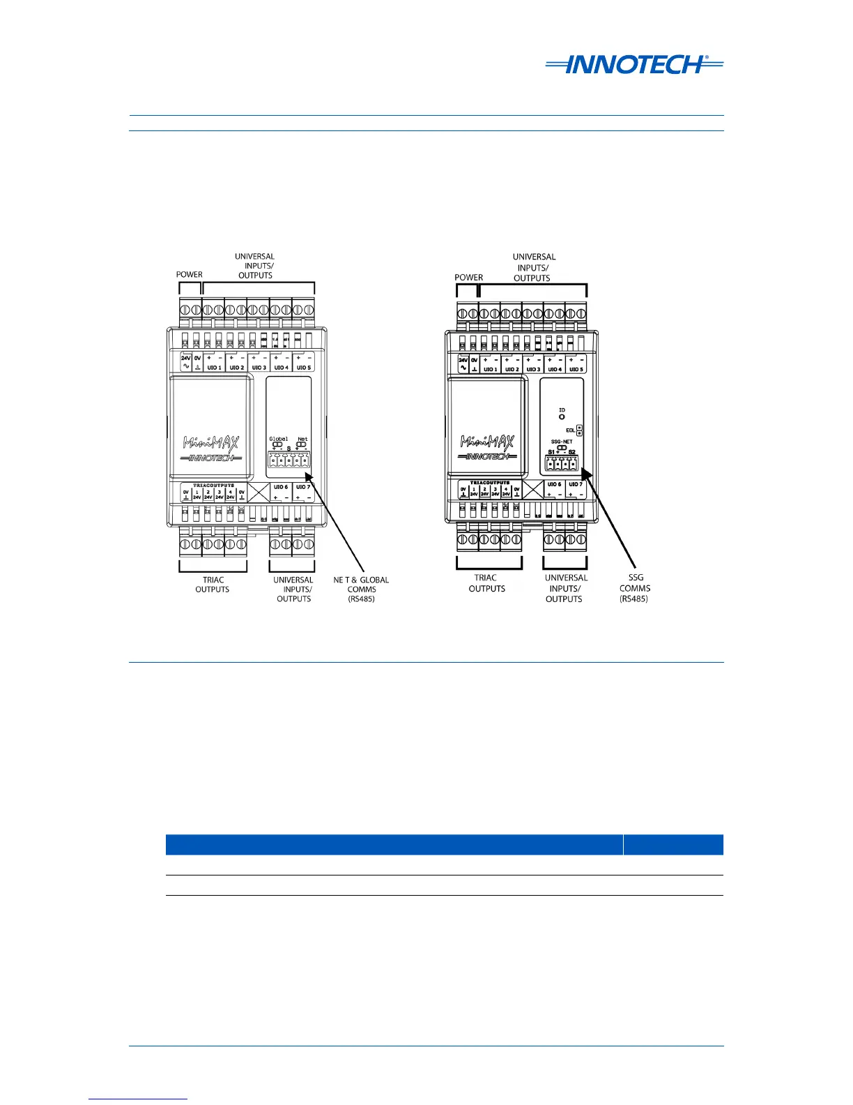
The general layout of the input and output terminals for each of these controllers is illustrated in
Figure 3-7 below.
3-3.2.1 Power Input
The MiniMAX controllers are powered by a 24V AC power source. The operating voltage must meet the
requirements of Safety Extra Low Voltage (SELV) to EN60730. The transformer used must be a Class 2
safety transformer in compliance with EN60742 and be designed for 100% duty. It must also be sized
and fused in compliance with local safety regulations. Power input specifications for the MiniMAX
controllers are detailed in Table 3-5 below.
Figure 3-7: MiniMAX (MM01 & MM02) Controller Terminal Connection Layout
Table 3-5: MiniMAX Power Source Specifications
Power Source Rating
24 VAC ±10%, 50/60 Hz, Nominal Transformer rating with maximum TRIAC load: 35VA
24 VAC ±10%, 50/60 Hz, Nominal Transformer rating with no TRIAC load: 10VA