Edition 2.0 dated 20/11/2013
3-3.2.3 TRIAC Outputs
The MiniMAX controllers are equipped with four TRIAC outputs used for switching the 24 VAC power
supply through to the outputs of the controller. There are four 24 V terminals for each TRIAC output,
and two 0 V terminals that are shared by the four TRIAC outputs. The TRIAC outputs are rated at
a minimum current of 20m A and maximum current of 250 m A. The TRIAC outputs can operate in
two modes: Pulse Width Modulation (PWM) or Digital (ON/OFF). The output range for both modes of
operation are described in Table 3-8 below.
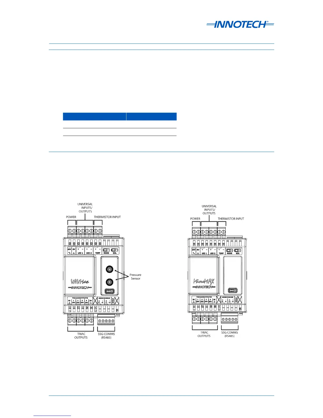
3-3.3 VAVMax and MicroMAX Controllers
This section of the manual provides wiring information for the VAVMax and MicroMAX controllers.
Information is provided on wiring a power source and all associated inputs and outputs.
The general layout of the input and output terminals for each of these controllers is illustrated in
Figure 3-8 below.
Table 3-8: MiniMAX Controllers: Modes of Operation for TRIAC Outputs
TRIAC Output Mode Output Range
Digital ON or OFF
PWM Output 0-100% (0-10VDC)
Figure 3-8: VAVMax and MicroMAX Controller Terminal Connection Layout