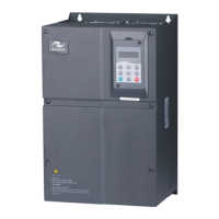
IS300 Series Servo Drive User Manual Wiring
- 27 -
Jumper positon indicates the position that could be seen when you face the terminal.
2.5 Description of Terminals of PG Card of IS300
SN Name Description
1 EXC
Excitation signal
2 /EXC
3 SIN
SIN feedback signal
4 SINLO
5 COS
COS feedback signal
9 COSLO
6
-- --7
8
■ Definition of IS300 Supporting Signal Lines (for Reference)
Definition EXC- EXC+ SIN+ SIN- COS+ COS-
Supporting encoder cable color Red Blue White Brown Yellow Green
Corresponding IS300 PG card pin 1 2 3 4 5 9
2.6 Wiring of External Braking Unit
2.6.1 Wiring of One External Braking Unit
Braking unit Servo drive
PB
P + - +
-
Braking resistor

 Loading...


