- 163 -
6 Trial Running
6
3)Stopatlimitswitchsignalactive:
● Denitions:
"Limitswitch":Themechanicalmovementgoesbeyondthedesignedrangeofsafemovement.
"Stopatlimitswitchsignalactive":Whenthemechanicalmovementgoesbeyondtherangeofsafemove-
ment, the limit switch outputs level change, and the servo drive forcibly stops the motor.
● Associatedparameters:
H02-07 Name
Stop mode at limit switch
signal
Setting &
Effective
At stop
Immediate
Data
Structure
-
Data
Format
Uint16
2002-08h Access RW Mapping -
Relevant
Mode
ALL
Data
Range
0–2 Default 1
It sets the deceleration mode of the servo motor from rotation to stop and the servo motor status when the limit
switch signal is active during motor running.
Value Stop Mode
0 Coasttostop,keepingthede-energizedstate
1 Stopatzerospeed,positionremainslocked
2 Stopatzerospeed,keepingde-energizedstate
Intheverticalaxisapplication,set2002-08h=1toxthemotoraxisinthepositionlockingstateafterthelimitswitch
signal is active to ensure safety.
Afterenablingthebrakeoutput,stopmodeatlimitswitchsignaloptionisforcedto"Stopatzerospeed,position
remainslocked."
Whenthelimitswitchsignalisactiveintheservomotor’sverticalaxisapplication,theworkpiecemightfall.
Topreventtheworkpiecefromfallingwhenthelimitswitchsignalisactive,set(2002-08h)to"1-Stopatzero
speed,thepositionremainslocked."Whentheworkmovesinlinear,makesuretoconnectthelimitswitchto
preventmechanicaldamage.Ifthelimitswitchsignalbecomesactive,enterareversereferencetomakethe
motor(workpiece)runinreversedirection.
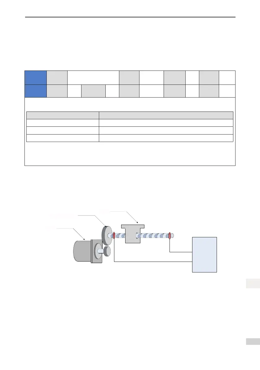
Figure 6-1 Installation diagram of limit switch
FunIN.14:
P-OT
FunIN.15:
N-OT
电机
减速轮
负载
伺服驱动器
DI
DI
To use the limit switch function, set two DI terminals of the servo drive respectively with function 14 (Fu-
nIN.14:P-OT, positivelimit switch)and function15(FunIN.15: N-OT,negativelimit switch)to receivethe
limit switch input level signals, and set the terminal logics. The servo drive determines whether to enable or
disable the limit switch function based on the DI terminal level.
Load
Servo drive
Reduction wheel
Motor

 Loading...


