1-5
System Components and Interconnections
Product Support: www.instron.com
System Components and Interconnections
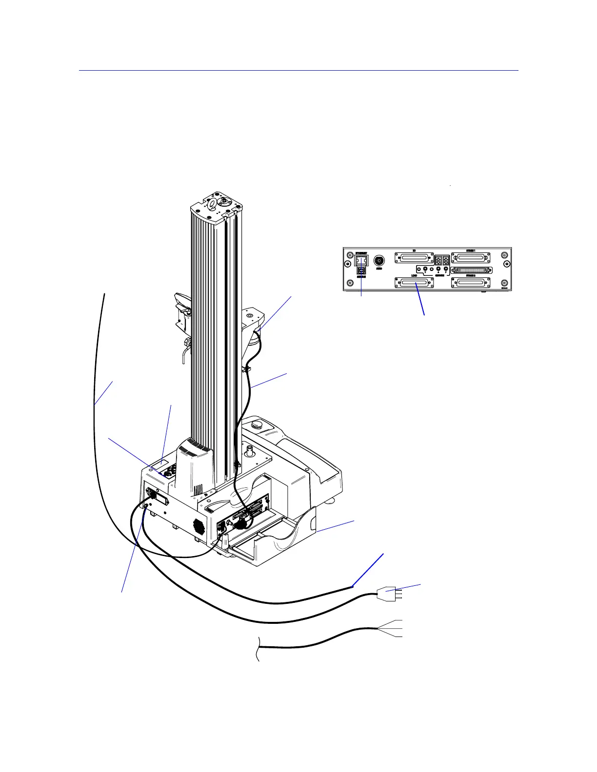
Figure 1-2 on page 1-5 shows you how each hardware component is connected to make up
the complete testing system.
Figure 1-2. 5940 System Connections
Load cell
Load cell
cable
Mains power cable
Ground stud
Computer interface
Ethernet crossover
cable
connection
Computer interface
connection
Controller cover
Load cell connector
Controller
Supplemental ground cable
GRN/YEL - Earth
BRN - Live
BLU - Neutral
System ID label
Options panel