2-9
Assemble the Load String
Product Support: www.instron.com
For example, for a standard ASTM tensile specimen (0.502 in wide, 0.125 in thick) made
with a material of tensile strength 5200 psi (from Materials Handbook) perform the
following calculation:
5200 x 0.502 x 0.125 = 328 lbf
This produces a recommendation of the 5 kN (1000 lb, 500kg) capacity load cell.
If you cannot determine an approximate value of tensile strength, use the highest capacity
load cell rated for the frame. Perform a preliminary test at a very slow speed to obtain the
load range required. You can then determine if a lower capacity load cell can provide
improved resolution.
Table 2-4 on page 2-9 lists the load cells that are recommended for use with 5940 Series
frames. If you have a load cell that is not listed, contact Instron for advice on compatibility
and adapters that may be available for your load cell.
Install the Load Cell
Check the following before installing a load cell:
The load cell installation drawings are available and you have all the parts that are
required for the installation.
Mounting screws are lubricated.
A torque wrench is available.
All threads, bores and mating surfaces are clean and free of damage.
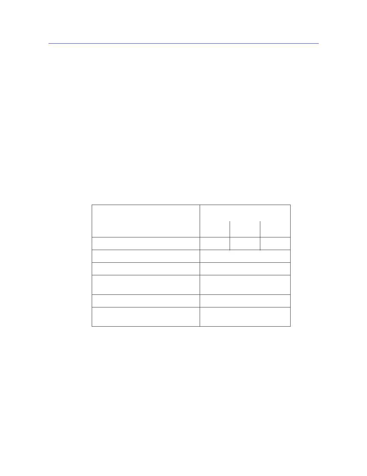
Table 2-4. Compatible Load Cells for 5940 Frames
Load Cell
Capacity
500 N 1 kN 2 kN
Catalog no. 2580-105 2580-106 2580-107
Weight - kg (lb) 0.6 (1.3)
Effective Length - mm (in) 100 (3.9)
Machine Interface M10 x 40 long x 1.5 pitch
RH central thread
Torque - load cell to machine - Nm (ft-lb) 19 (14)
Accessory Interface Integral type O (female)
12 mm clevis with 6 mm clevis pin