Chapter: Preparing the System
2-10 M10-16245-EN
The crosshead is positioned below its travel midpoint so that you can easily and safely
access the crosshead.
The crosshead is stationary and the TEST IN PROGRESS indicator light is not
illuminated.
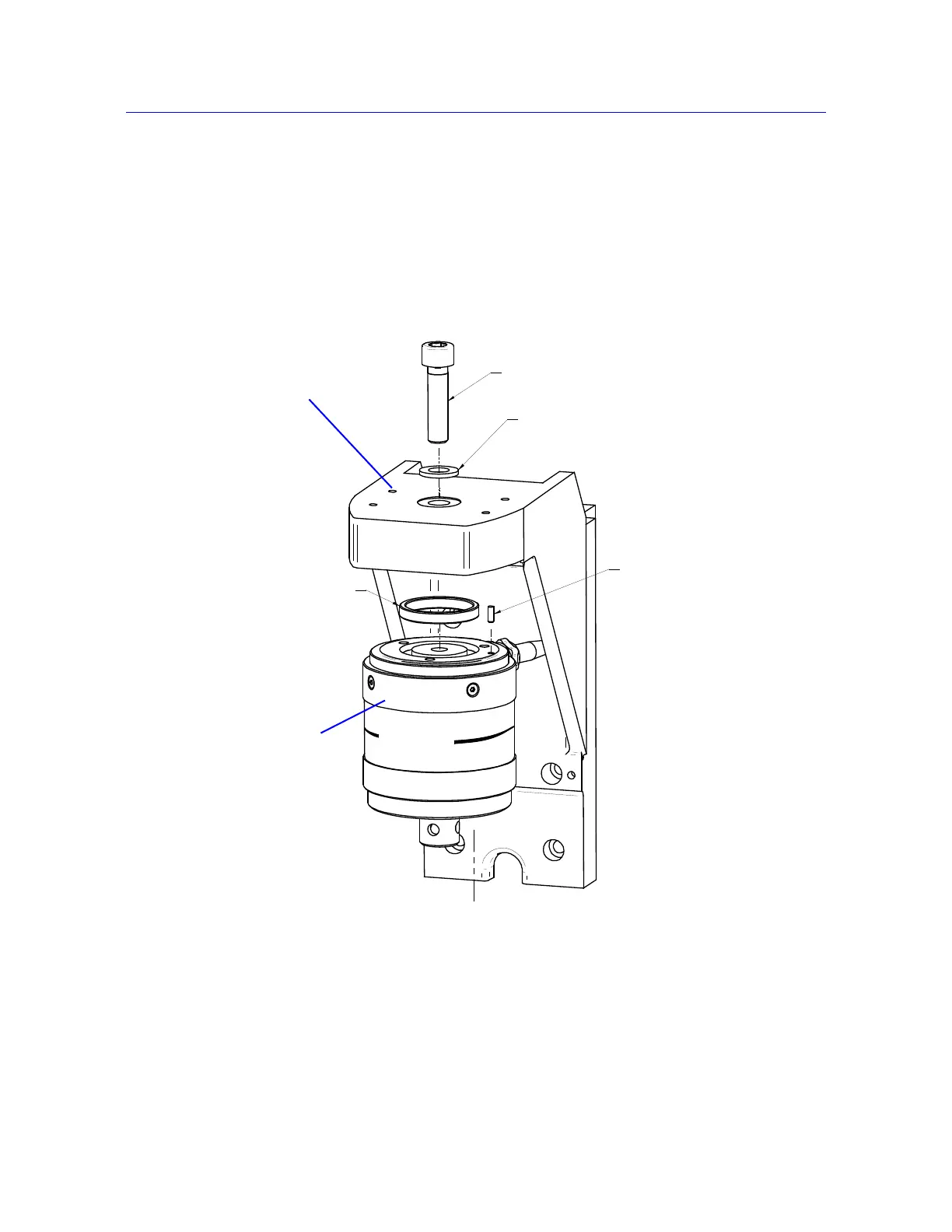
Refer to Figure 2-4 on page 2-10 and perform the following procedure.
Load cell installation procedure:
1. Refer to the load cell installation drawing and collect together the correct mounting
screw, washer, anti-rotation pin and locating ring for your combination of load frame
and load cell.
Figure 2-4. Installing the Load Cell