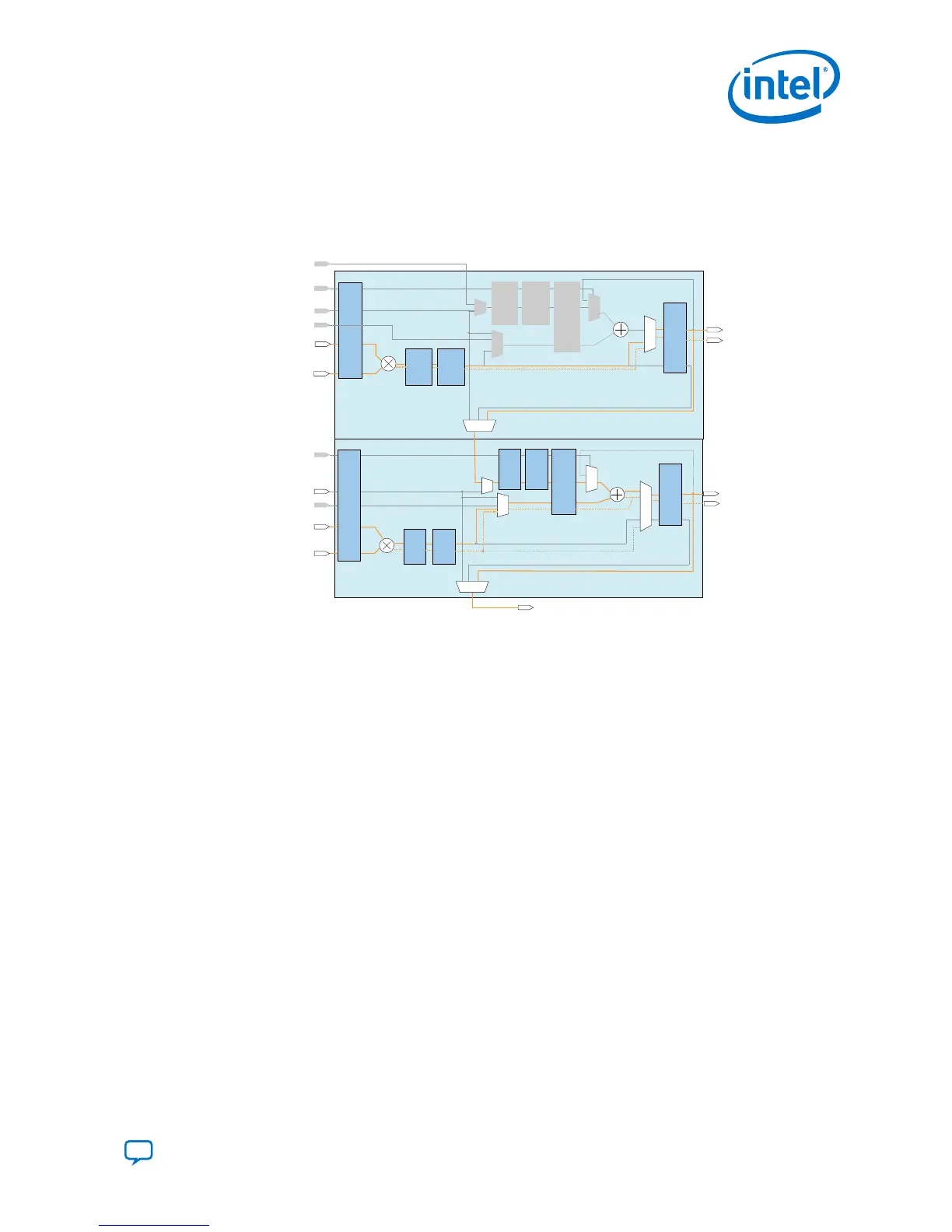
The imaginary part [(a × d) + (b × c)] is implemented in the first two variable-
precision DSP blocks, while the real part [(a × c) - (b × d)] is implemented in the next
two variable-precision DSP blocks.
Figure 43. Complex Multiplication with Imaginary Result Using FP32 Single-Precision
Floating-Point Arithmetic
a
d
b
c
Result Imaginary
Multiplication Mode
*This block diagram shows the functional representation of the DSP block.
The pipeline registers are embedded within the various circuits of the DSP block.
fp32_chainout[31:0]
fp32_chainin[31:0]
accumulate
fp32_adder_a[31:0]
fp32_mult_b[31:0]
fp32_mult_b31:0]
Output
Register
Bank
fp32_result[31:0]
Input
Register
Bank
Multiplier
Adder
*Pipeline
Register
Bank
*Pipeline
Register
Bank
Register
Bank
*Pipeline
Register
Bank
*Pipeline
Register
Bank
fp32_mult_invalid
fp32_mult_inexact
fp32_mult_overflow
fp32_mult_underflow
*Pipeline
fp32_adder_b[31:0]
fp32_chainout[31:0]
fp32_chainin[31:0]
accumulate
fp32_adder_a[31:0]
fp32_result[31:0]
Multiplier
Adder
*Pipeline
Register
Bank
*Pipeline
Register
Bank
Register
Bank
*Pipeline
Register
Bank
*Pipeline
Register
Bank
fp32_mult_invalid
fp32_mult_inexact
fp32_mult_overflow
fp32_mult_underflow
fp32_adder_invalid
fp32_adder_inexact
fp32_dder_overflow
fp32_adder_underflow
*Pipeline
Output
Register
Bank
Input
Register
Bank
fp32_adder_b[31:0]
fp32_mult_a[31:0]
fp32_mult_b[31:0]
Multiply-Add Mode
3. Intel Agilex Variable Precision DSP Blocks Operational Modes
UG-20213 | 2019.04.02
Send Feedback
Intel
®
Agilex
™
Variable Precision DSP Blocks User Guide
59

 Loading...


