Intel
®
Core
TM
2 Duo E6400, E4300, and Intel
®
Pentium
®
Dual-Core E2160 Processor—Processor
Thermal/Mechanical Information
Intel
®
Core
TM
2 Duo E6400, E4300, and Intel
®
Pentium
®
Dual-Core E2160 Processor
TDG October 2007
16 Order Number: 315279 -003US
2.2.3 T
CONTROL
T
CONTROL
defines the maximum operating temperature for the digital thermal sensor
when the thermal solution fan speed is being controlled by the digital thermal sensor.
The T
CONTROL
parameter defines a very specific processor operating region where fan
speed can be reduced. This allows the system integrator a method to reduce the
acoustic noise of the processor cooling solution, while maintaining compliance to the
processor thermal specification.
Note: The T
CONTROL
value for Intel® Core™2 Duo desktop E6400,E4300, and Intel® Pentium®
Dual-Core E2160 processor is relative to the Thermal Control Circuit (TCC) activation
set point which will be seen as 0 (zero) when using the digital thermal sensor. As a
result, the T
CONTROL
value will always be a negative number. Refer to Chapter 4.0 for a
discussion on thermal management logic and features and Chapter 6.0 on Intel® Quiet
System Technology (Intel® QST).
The value of T
CONTROL
is driven by a number of factors. One of the most significant of
these is the processor idle power. As a result, a processor with a high T
CONTROL
will
dissipate more power than a part with lower value of T
CONTROL
when running the same
application.
The value of T
CONTROL
is calculated such that regardless of the individual processor's
T
CONTROL
value, the thermal solution should perform similarly. The higher power of some
parts is offset by a higher value of T
CONTROL
in such a way that they should behave
virtually the same acoustically. This is achieved in part by using the Ψ
CA
vs. RPM and
RPM versus acoustics (dBA) performance curves from the Intel enabled thermal
solution. A thermal solution designed to meet the thermal profile should have similar
acoustic performance for any value of T
CONTROL
.
The value for T
CONTROL
is calculated by the system BIOS based on values read from a
factory configured processor register. The result can be used to program a fan speed
control component. Refer to the appropriate datasheet for more details on reading the
register and calculating T
CONTROL
.
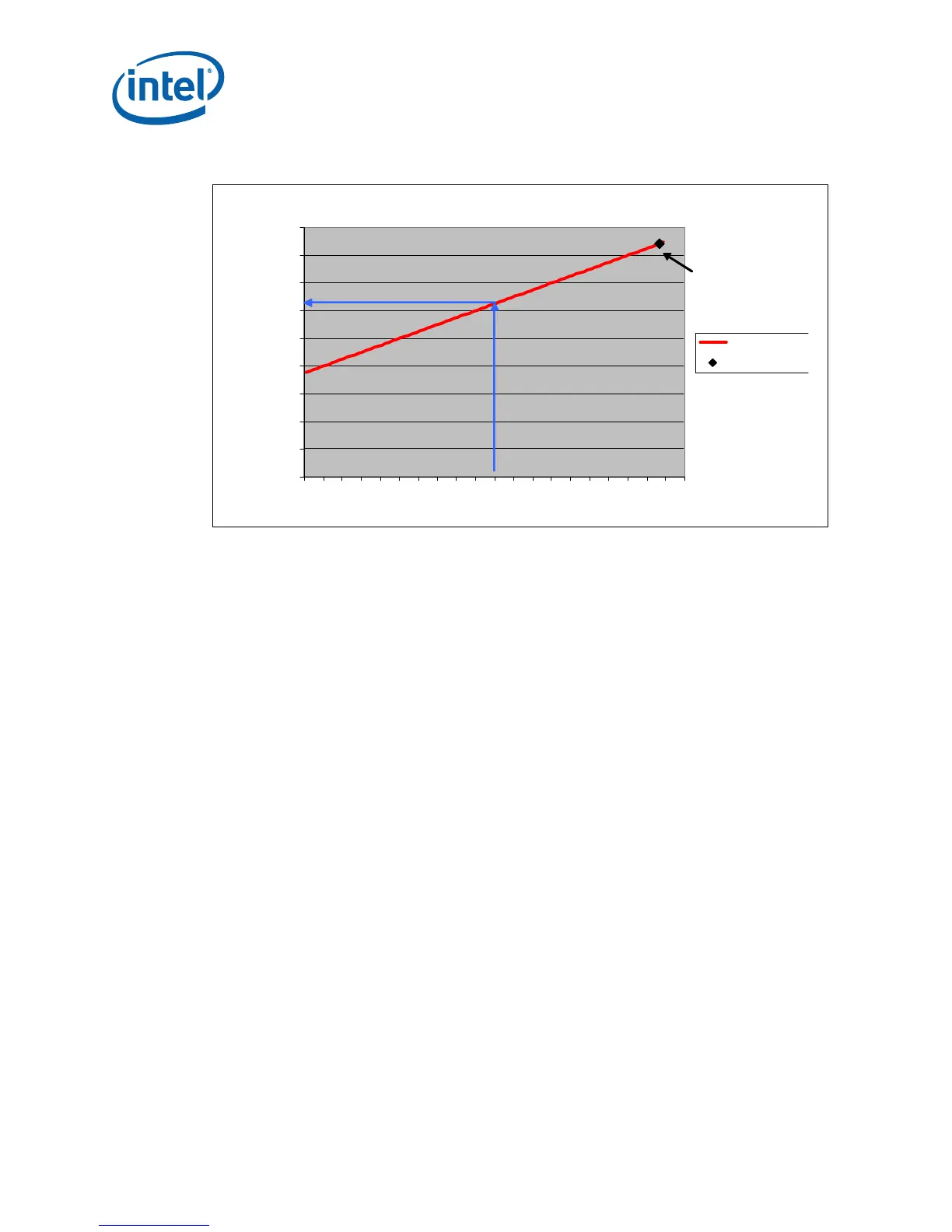
Figure 3. Example Thermal Profile
30
35
40
45
50
55
60
65
70
75
30 40 50 60 70 80 90 100 110
Watts
Case Temperature (C)
Thermal Profil
TDP
Heatsink
Design Point
 Loading...


