54 523462
Intel Confidential
Flash Image Tool
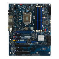
To set the size of each flash component, expand the “Descriptor Region” tree node and
select the “Component Section” node. The parameters “Flash component 1 density”
and “Flash component 2 density” specify the size of each flash component. Double-click
on each parameter and select the correct component size from the drop-down list. Click
“OK” to update the parameters.
Note: The size of the second flash component will only be editable if the number of flash
components is set to 2.
The Upper and Lower Flash Erase sizes and Flash Partition Boundary address is not
editable from this view. In order to modify these entries you must enter the Build
Settings dialog box. Note that asymmetric flash parts are no longer supported.
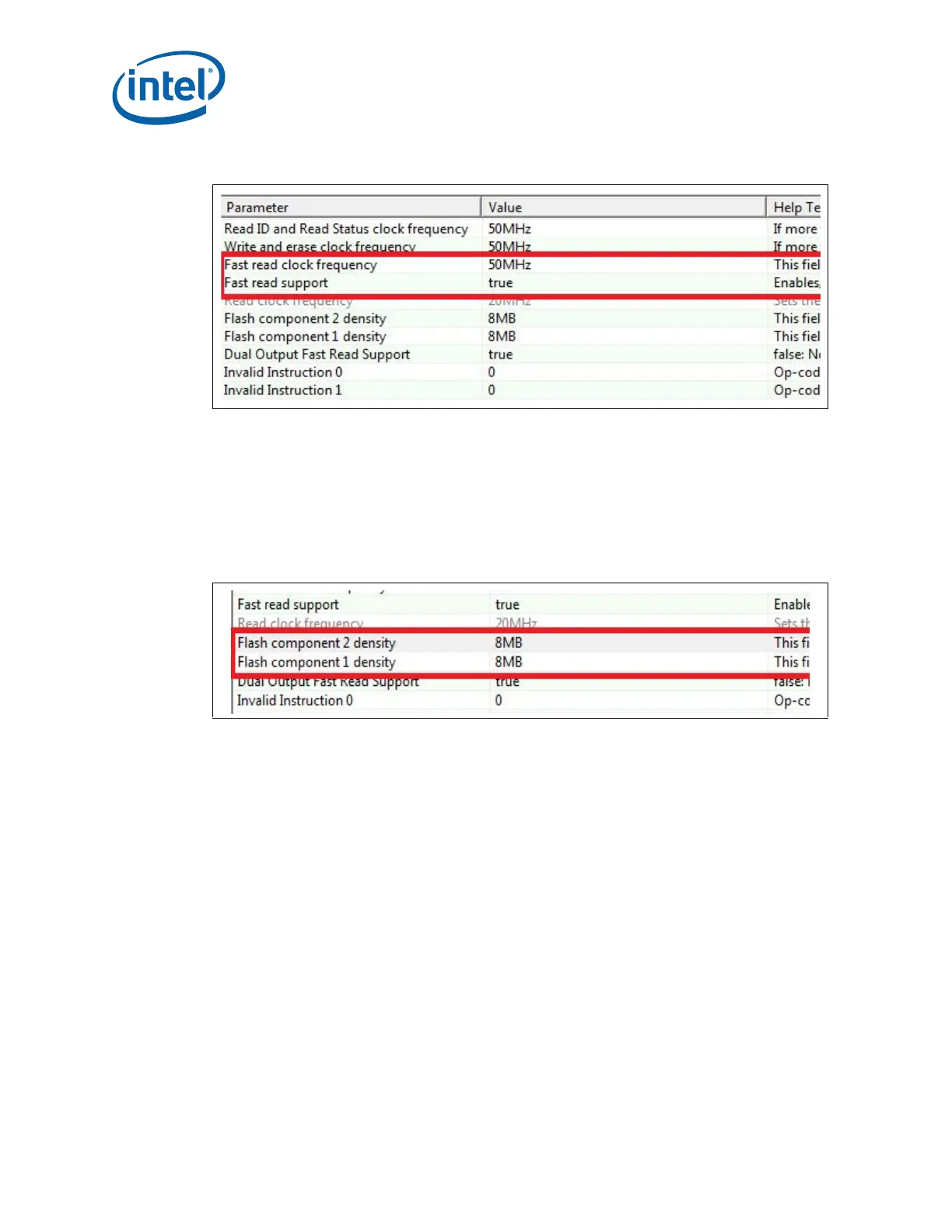
Figure 7-4. Descriptor Region – Fast Read Support Options
Figure 7-5. Descriptor Region - Component Section Options