Intel
®
Pentium
®
III Processor with 512KB L2 Cache Dual Processor Platform Design Guide 8-1
System Design Checklist 8
8.1 Introduction
This checklist highlights design considerations that should be reviewed prior to manufacturing a
motherboard that implements an Intel
®
Pentium
®
III Processor with 512KB L2 Cache system design.
This is not a complete list and does not guarantee that a design will function properly. Besides the items
in the following text, refer to the most recent version of the design guide for more detailed instructions on
designing a motherboard.
8.2 Design Checklist Summary
The following tables contain design considerations for the various portions of a design. Each table
describes one portion and is titled accordingly.
8.3 Host Interface AGTL Bus and AGTL Signals
It is strongly recommended that AGTL signals be routed on signal layers next to the ground layer. It is
important to provide effective signal return paths with low inductance.
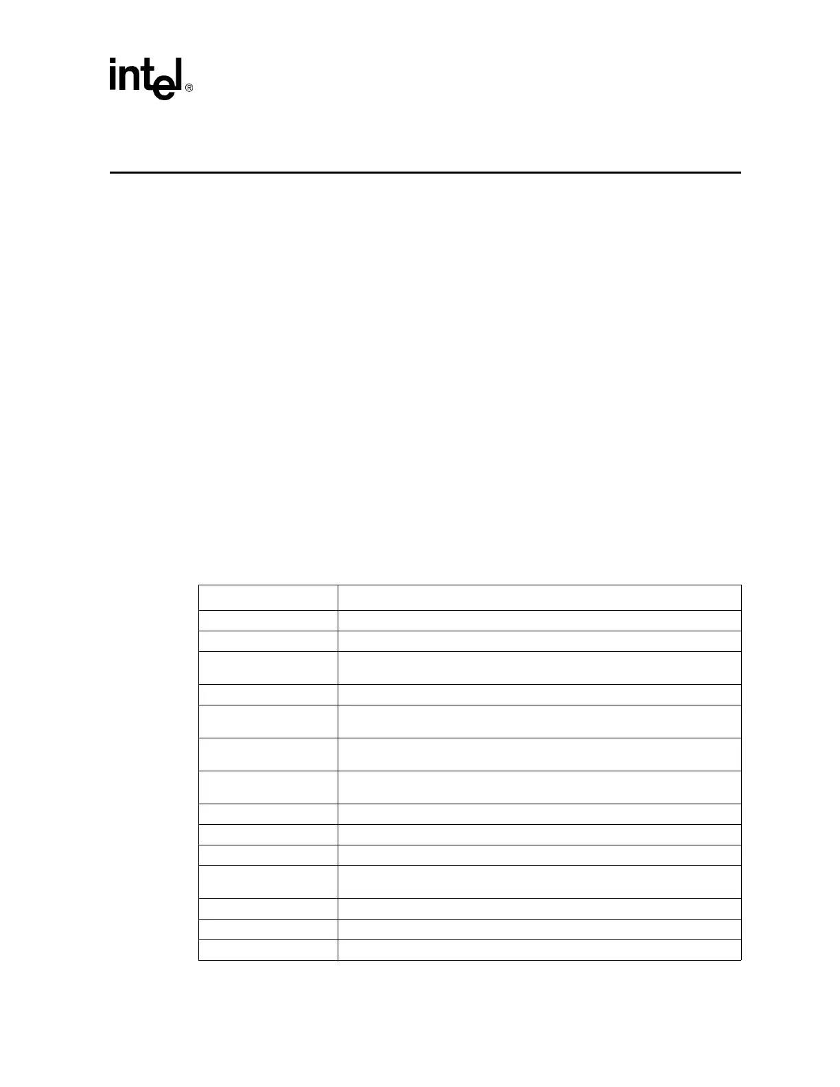
Table 8-1. AGTL Signals (Sheet 1 of 2)
CPU Pin Pin Connection
A[35:3]# Connect to chipset and second CPU.
ADS# Connect to chipset and second CPU.
AERR#
Connect to chipset and second CPU. Pull up to V
TT
through a 150W resistor at
chipset. See Wired-OR section for details.
AP[1:0]# Connect to chipset and second CPU.
BERR#
Connect to chipset and second CPU. Pull up to V
TT
through a 150W resistor at
chipset. See Wired-OR section for details
BINIT#
Connect to chipset and second CPU. Pull up to V
TT
through a 150W resistor at
chipset. See Wired-OR section for details
BNR#
Connect to chipset and second CPU. Pull up to V
TT
through a 150W resistor at
chipset. See Wired-OR section for details
BP[3:2]# Leave as N/C.
BPM[1:0] Leave as N/C.
BPRI# Connect to chipset and second CPU.
BR0#
Connect BR0# from CPU0 to BR1# of CPU1. Connect BREQ0# of CPU0 to
BR0# of chipset.
BR1# Connect BR1# from CPU0 to BR0# of CPU1.
D[63:0]# Connect to chipset and second CPU.
DBSY# Connect to chipset and second CPU.