8-2 Intel
®
Pentium
®
III Processor with 512KB L2 Cache Dual Processor Platform Design Guide
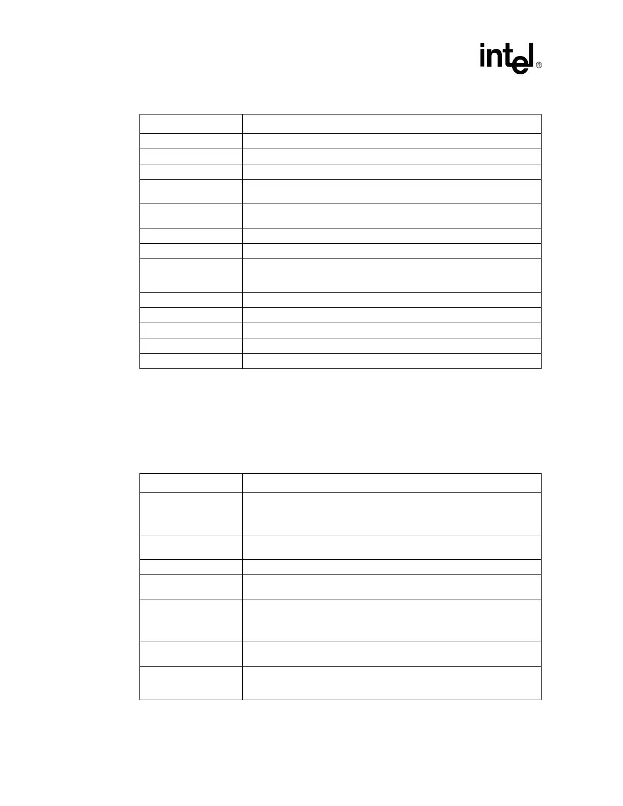
8.4 CMOS (Non-AGTL) Signals
It is recommended to route CMOS signal traces on one signal layer, and not next to AGTL traces. Try to
avoid long traces to eliminate speed path issues, especially for APIC clock and APID data signals.
DEFER# Connect to chipset and second CPU.
DEP[7:0]# Connect to chipset and second CPU.
DRDY# Connect to chipset and second CPU.
HIT#
Connect to chipset and second CPU. Pull up to V
TT
through a 150Ω resistor at
chipset. See Wired-OR section for details
HITM#
Connect to chipset and second CPU. Pull up to V
TT
through a 150Ω resistor at
chipset. See Wired-OR section for details
LOCK# Connect to chipset and second CPU.
REQ[4:0]# Connect to chipset and second CPU.
RESET#
86 Ω pull-uptoV
TT
tied to 22 Ω series resistor to a 10 pF cap to ground, connect
to chipset and second CPU. Connect to ITP pin 2 (RESET#) with 240 Ω series
resistor and 68Ω pull-up to V
TT
.
RESET2# Not Connected
RP# Connect to chipset and second CPU.
RS[2:0]# Connect to chipset and second CPU.
RSP# Connect to chipset and second CPU.
TRDY# Connect to chipset and second CPU.
Table 8-2. CMOS Signals (Sheet 1 of 2)
CPU Pin Pin Connection
A20M#
Connect to second CPU and pull up through ~330 Ω to VccCMOS. May also
need to be connected to chipset or compatibility logic. For boards supporting
preproduction processors, this pin must be connected to frequency selection
circuitry.
FERR#
Connect to second CPU and pull up through ~150 Ω to VccCMOS. May need to
connect to chipset or server management logic.
FLUSH# Connect to second CPU and pull up through ~150 Ω to VccCMOS
IERR#
Pull up through ~150 Ω to VccCMOS if connected to external logic. Leave
unconnected otherwise.
IGNNE#
Connect to second CPU and pull up through ~330 Ω to VccCMOS. May also
need to be connected to chipset or compatibility logic. For boards supporting
preproduction processors, this pin must be connected to frequency selection
circuitry.
INIT#
Connect to second CPU and pull up through ~330 Ω to VccCMOS. May also
need to be connected to chipset or compatibility logic.
LINT0/INTR
Connect to interrupt control logic and second CPU and pull up through ~330 Ω to
VccCMOS. For boards supporting preproduction processors, this pin must be
connected to frequency selection circuitry.
Table 8-1. AGTL Signals (Sheet 2 of 2)
CPU Pin Pin Connection