3-6 Intel
®
Pentium
®
III Processor with 512KB L2 Cache Dual Processor Platform Design Guide
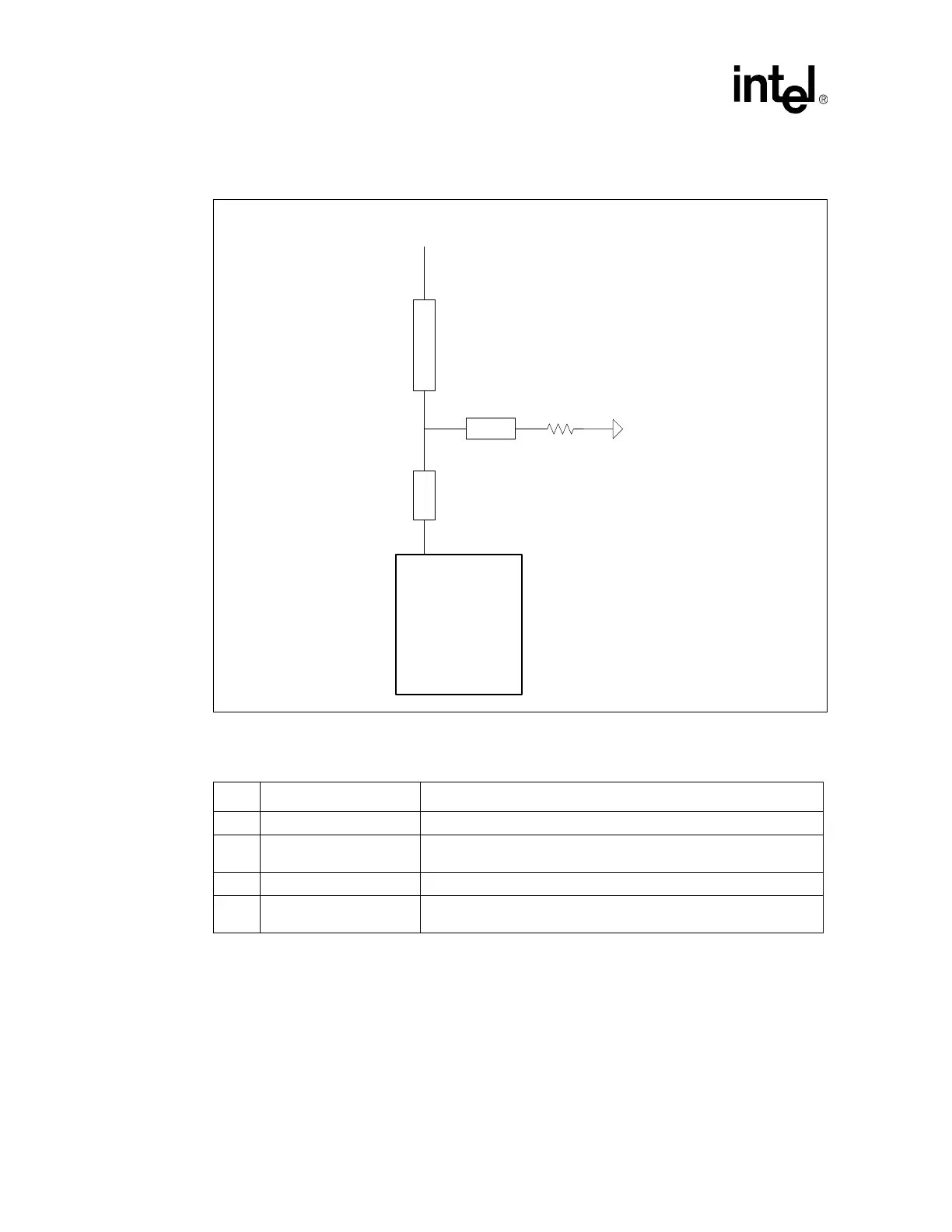
Please note that the value range for R1 present a set of trade-offs for flight time and dampening effects.
Choosing a value near the upper end of the range (around 200Ω) will impact the flight times the least, but
will also provide minimal dampening. Choosing a value at the lower end of the range (around 100Ω)will
provide optimal dampening but has a larger impact on the signal flight times. Intel recommends a value
of 150Ω +/- 10% as a reasonable trade-off between dampening and flight time.
Figure 3-3. Wired-OR Termination Topology
Table 3-9. Wired-OR Values
Item Value Notes
L1 1.75 to 2.5 inches Same as L2 lengths in Section 3.2 and Section 3.3
L2 Less than 0.25 inches
Should be as short as possible. Optimal case is to make this value
zero, making the L3 stub come after the chipset pin.
L3 Less than 1.5 inches
R1 100 to 220 Ω
The range of values has trade-offs in flight time and dampening effects.
150Ω +/- 10% is a base recommendation.
L1
Vtt
L3
L2
Chipset "T" Stub
Chipset
R1