Intel
®
Pentium
®
III Processor with 512KB L2 Cache Dual Processor Platform Design Guide 5-7
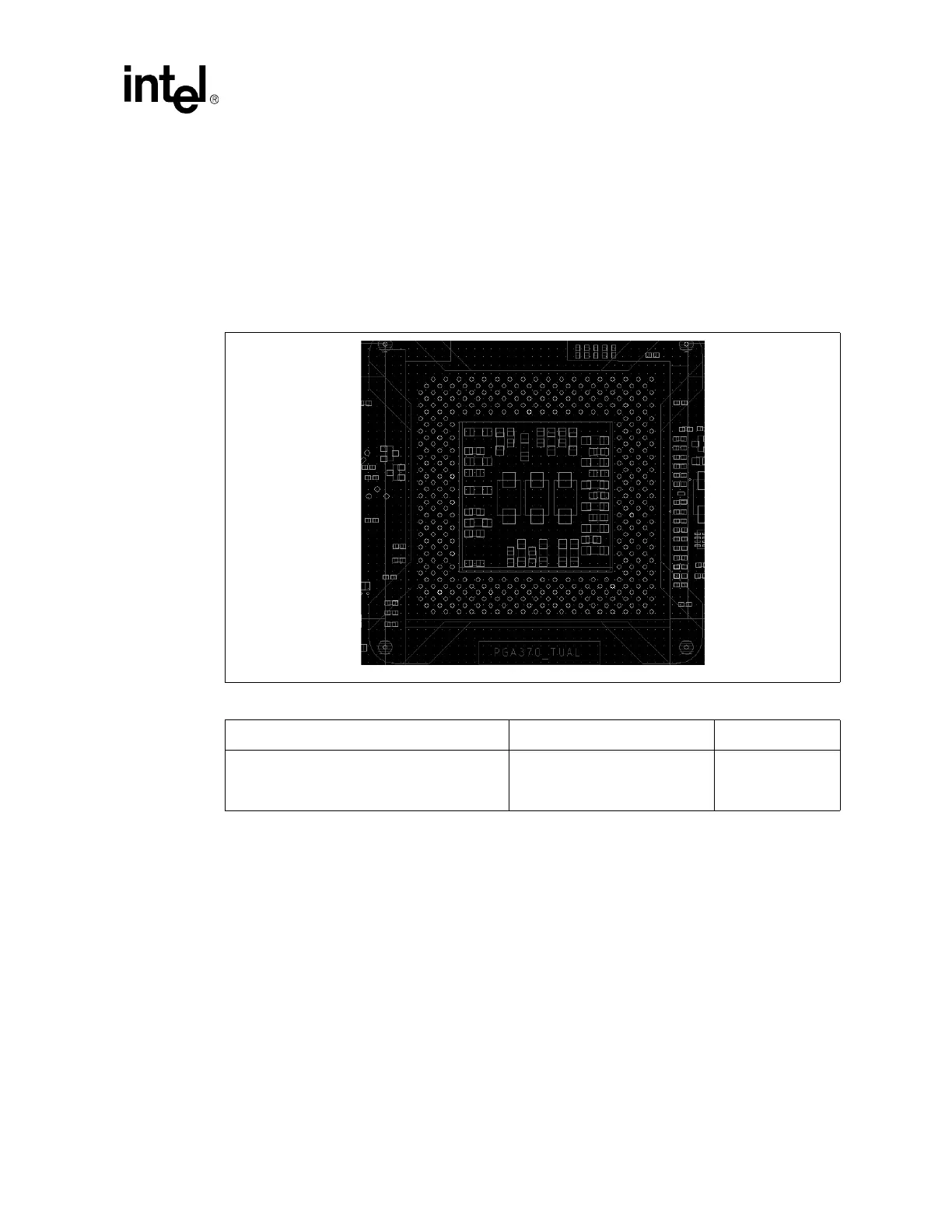
5.5.1 Decoupling Guidelines
5.5.1.1 Vcc
CORE
Decoupling Design
Table 5-2 contains the quantities and values for the Vcc
CORE
supply high frequency decoupling. All
capacitors should be placed within the PGA370 socket cavity and mounted on the primary side of the
motherboard. The capacitors are arranged to minimize the overall inductance between Vcc
CORE
and V
SS
power pins, as shown in Figure 5-6.
5.5.1.2 V
TT
Decoupling Design
Twenty 0.1-µF capacitors in 0603 packages should be placed within 200 mils of each PGA370 socket. As
many of these capacitors should be placed inside the PGA370 socket cavity.
5.5.1.3 AGTL V
REF
Decoupling Design
Three 0.1-µF capacitors in 0603 packages should be placed within 500 mils of the V
REF
pins. Two should
be connected between V
TT
and V
REF
, and one should be connected between V
REF
and ground. If this
circuit is far from the processor, add a 0.1-uF capacitor for decoupling.
Figure 5-6. PGA370 Decoupling Capacitor Placement
Table 5-2. Vcc
CORE
High Frequency Capacitance Recommendations
Capacitance ESR ESL
9 1210 package, 22µF
or
16 1206 package, 4.7µF
10mΩ 1.1 nH