Intel
®
Pentium
®
III Processor with 512KB L2 Cache Dual Processor Platform Design Guide 3-3
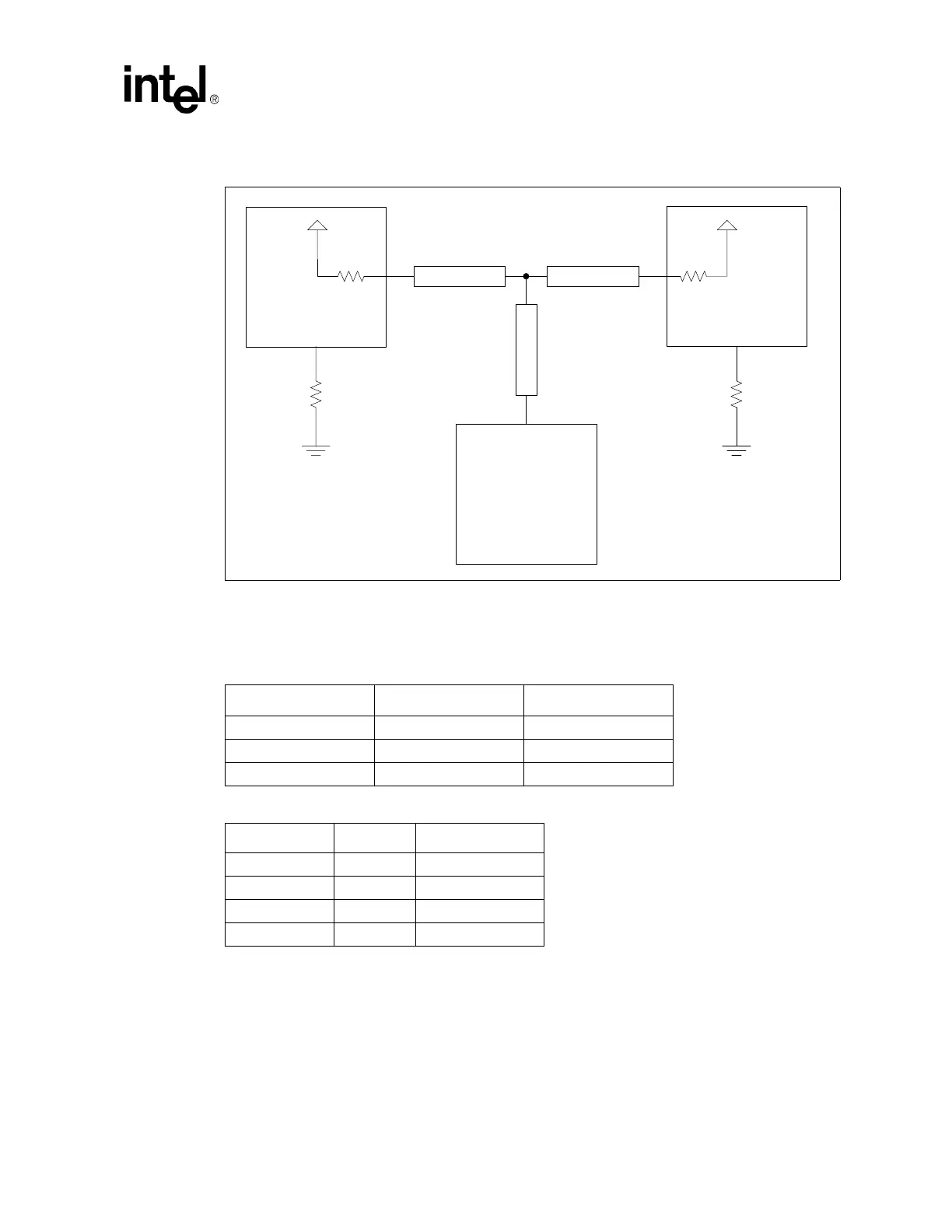
Table 3-5 contains the length specifications for the segments of the T-topology. Please note that lengths
L0 and L1 must be length matched to within 0.25 inches. Table 3-6 contains the component values which
should be used for this topology.
Figure 3-1. System Bus T-Topology
Table 3-5. Trace Lengths for T Topology (ServerWorks Chipset)
Segment Min Length (inches) Max Length (inches)
L0 3.25 3.75
L1 3.25 3.75
L2 1.75 2.5
Table 3-6. Component Values for T Topology
Reference Value Tolerance
R1 (on chip) 68Ω 10%
R2 (on chip) 68Ω 10%
R3 68Ω 1%
R4 68Ω 1%
Chipset
CPU0
CPU1 or
Terminator
L0 L1
L2
RTTCTRL
V
TT
R1 R2
V
TT
R3
RTTCTRL
R4