3-14 Intel
®
Pentium
®
III Processor with 512KB L2 Cache Dual Processor Platform Design Guide
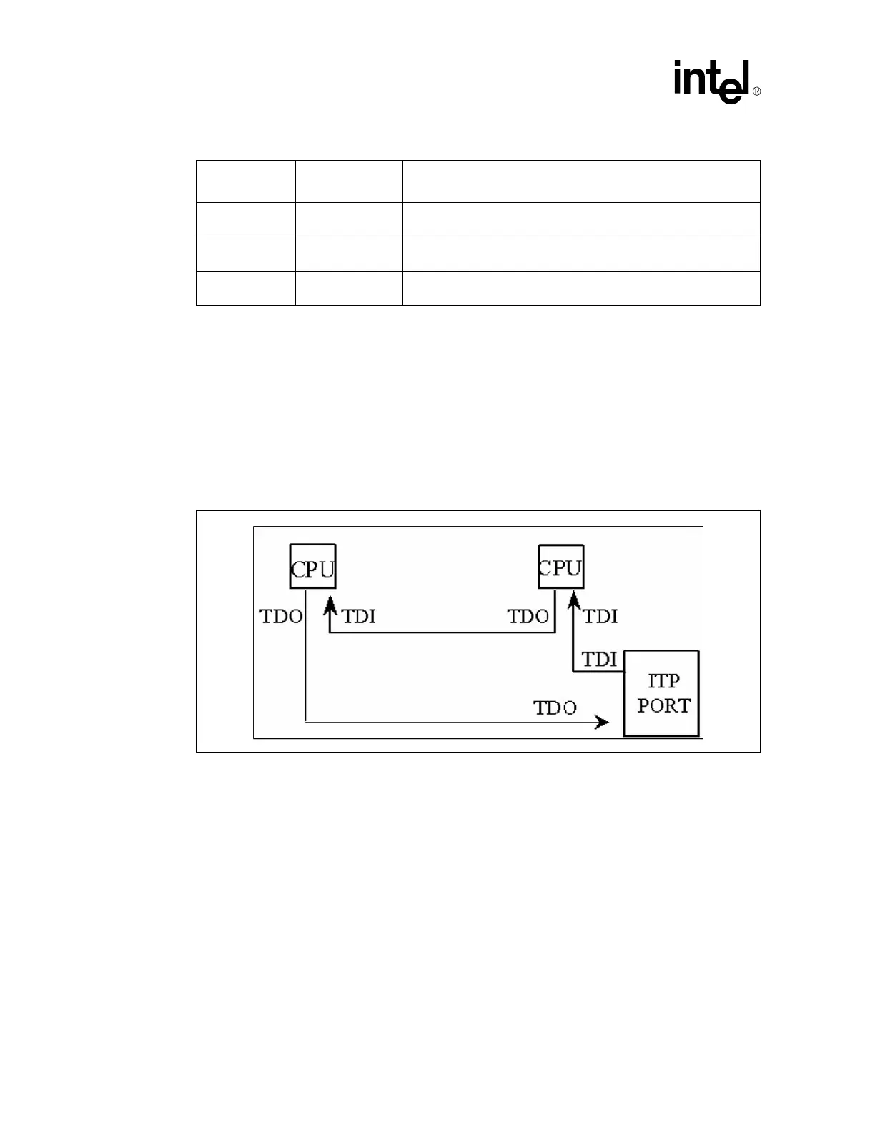
3.10.1.4 System Implementation
Figure 3-8 demonstrates the expected route of the JTAG data link for a processor only cluster. It is
obligatory to pull up TDI/TDO for each signal, however. Note that when the number of processors is
changed, a bypass must be used for the empty sites.
Figure 3-9 and Figure 3-10 illustrate possible bypass configurations with a three pin jumper and a four-
pin jumper.
TRST# Figure 3-4b
1" max from debug port to RT AND 12" max from debug port to
processor
PRDYx# Figure 3-6
1" max from debug port to RS AND 1" max from debug port to RT
AND 12" max from debug port to processor (AGTL guidelines)
RESET# Figure 3-7
1" max from debug port to RS AND 1" max from debug port to RT
AND 12" max from debug port to processor
Figure 3-8. JTAG Signals TDI/TDO for Processor Only
Table 3-14. Routing Guidelines
Parameter
Reference
Figure
Description