Thin Mini-ITX Internal Electrical Interfaces
Thin Mini-ITX Based PC System Design Guide 19
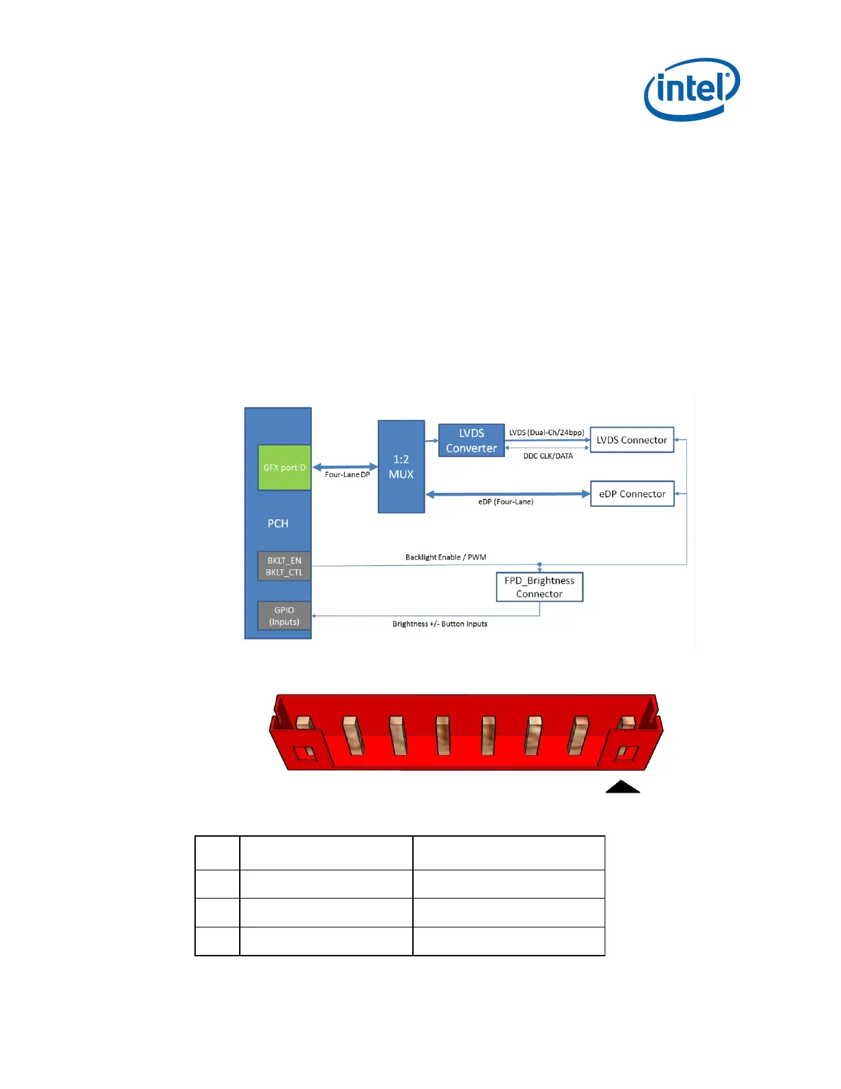
2.2.3 Flat Panel Display Brightness
The motherboard must provide an additional connector for powering the inverter or
driver board. An 8-pin FPD_Brightness connector must be 1x8 shrouded, 2.00mm
pitch with 2A rating per pin as shown in the below figure. The connector must also
provide backlight enable and control signals, as well as input pins for brightness
up/down front panel button control signals. The 8-pin FPD Brightness connector must
be validated to support maximum power delivery at 19 Volts, as well as to correctly
support backlight enable/control and brightness up/down signals.
An assortment of LVDS flat panels with CCFL and LED backlights should be used for
validating backlight power and control features.
Backlight brightness must be dynamically controlled via discrete flat panel
brightness buttons.
Figure 2-3. PC & Software Brightness Control:
Figure 2-4. FPD Brightness Header
Table 2-4. 8-pin FPD Brightness Header Pin-Out