Thin Mini-ITX Internal Electrical Interfaces
Thin Mini-ITX Based PC System Design Guide 21
2.3 Audio
2.3.1 Front Panel Audio
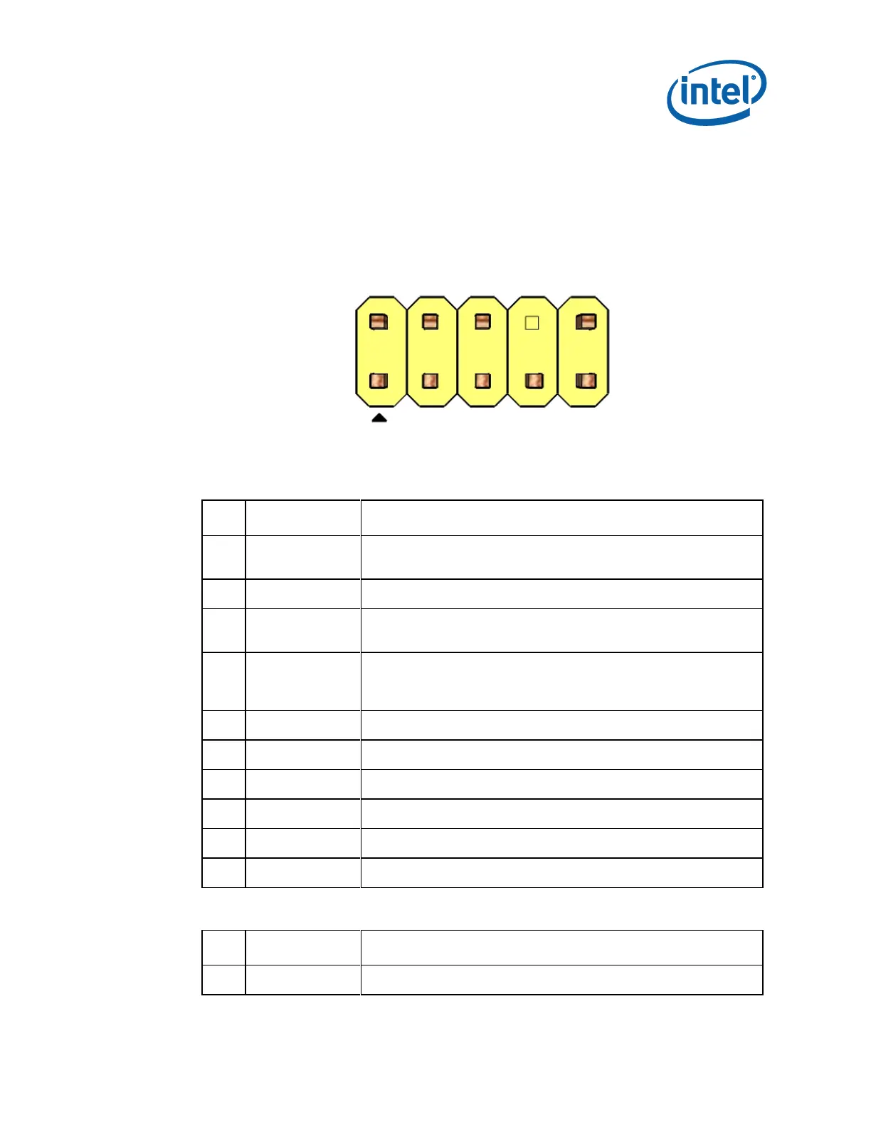
Front panel audio header: 2x5, 2.54mm pitch, keyed at pin 8
Figure 2-5. Front Panel Audio Header
Table 2-5. Passive AC’97 Front Panel Audio Header Pin-Out
Front panel microphone input signal (biased when supporting
stereo microphone)
Ground used by analog audio circuits
Microphone power / additional MIC input for stereo microphone
support
Active low signal that signals BIOS that an Intel® HD Audio dongle
is connected to the analog header. PRESENCE# = 0 when an
Intel® HD Audio dongle is connected.
Right channel audio signal to front panel (headphone drive capable)
Ground used by analog audio circuits
Left channel audio signal to front panel (headphone drive capable)
Ground used by analog audio circuits
Table 2-6. HD Audio Front Panel Audio Header Pin-Out
Analog Port 1 - Left channel (Microphone)