Mechanical
50 Thin Mini-ITX Based PC System Design Guide
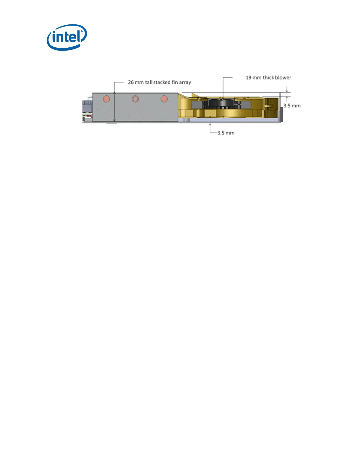
Figure 5-6. Minimum Blower Gap
The free mass of a CPU thermal solution that does not attach directly to the
motherboard must be supported by the chassis. As an example, the typical AIO CPU
thermal solution consists of a CPU cold plate, heat exchanger and blower. The heat
exchanger and blower are typically located outside the boundary of the motherboard
footprint. Therefore, the blower and heat exchanger mechanical attach must be
designed by the chassis supplier with the targeted thermal solution in mind. The cold
plate of the CPU thermal solution must be designed to attach directly to the
motherboard via fasteners that ship with the thermal solution.
The Low Profile reference thermal solution described in Section 6 is an example of the
type of thermal solution targeted for this type of form factor. It consists of a cold
plate, heat pipes, and stacked fin array. By design, the stacked fin array will sit onto
the chassis bottom pan. The fin stack is suspended beyond the edge of the
motherboard by three heat pipes. This type of thermal solution design must be
physically constrained in the positive Z direction in the region of the stacked fins of
the heatsink so that the heat pipes do not bend during a mechanical shock load in the
positive Z direction, i.e. perpendicular to the motherboard plane. Likewise, the
heatsink stacked fin section must be physically constrained from movement in the
plane of the motherboard during a mechanical shock loading event which occurs in the
same plane as the motherboard.
5.5 Thin Mini-ITX I/O Shield
As the specific side I/O ports can vary from motherboard to motherboard, it is
recommended that a chassis keep the chassis I/O as an open aperture that is filled by
the motherboard’s I/O shield. A chassis could develop plastic molding in this area that
is contoured to the industrial design and the specific connector pattern of a
motherboard; however, this removes the chassis’ ability to use motherboards with
different I/O patterns.
The below figure is an example of a Thin Mini-ITX I/O shield that would ship with a
Thin Mini-ITX motherboard.