EasyManuals Logo

Intel Thin Mini-ITX User Manual

Intel Thin Mini-ITX
67 pages
To Next Page IconTo Next Page
To Previous Page IconTo Previous Page
Page #29 background imageLoading...
Page #29 background image
Thin Mini-ITX Internal Electrical Interfaces
Thin Mini-ITX Based PC System Design Guide 29
Table 2-13. Front Panel Main Header Pin-Out
Pin
Signal Name
Description
1
HDD_POWER_LED
Pull-up resistor to +5V
2
POWER_LED_MAIN
[Out] Front panel LED (main color)
3
HDD_LED#
[Out] Hard disk activity LED
4
POWER_LED_ALT
[Out] Front panel LED (alt color)
5
GROUND
Ground
6
POWER_SWITCH#
[In] Power switch
7
RESET_SWITCH#
[In] Reset switch
8
GROUND
Ground
9
+5V_DC
Power
10
KEY
No pin
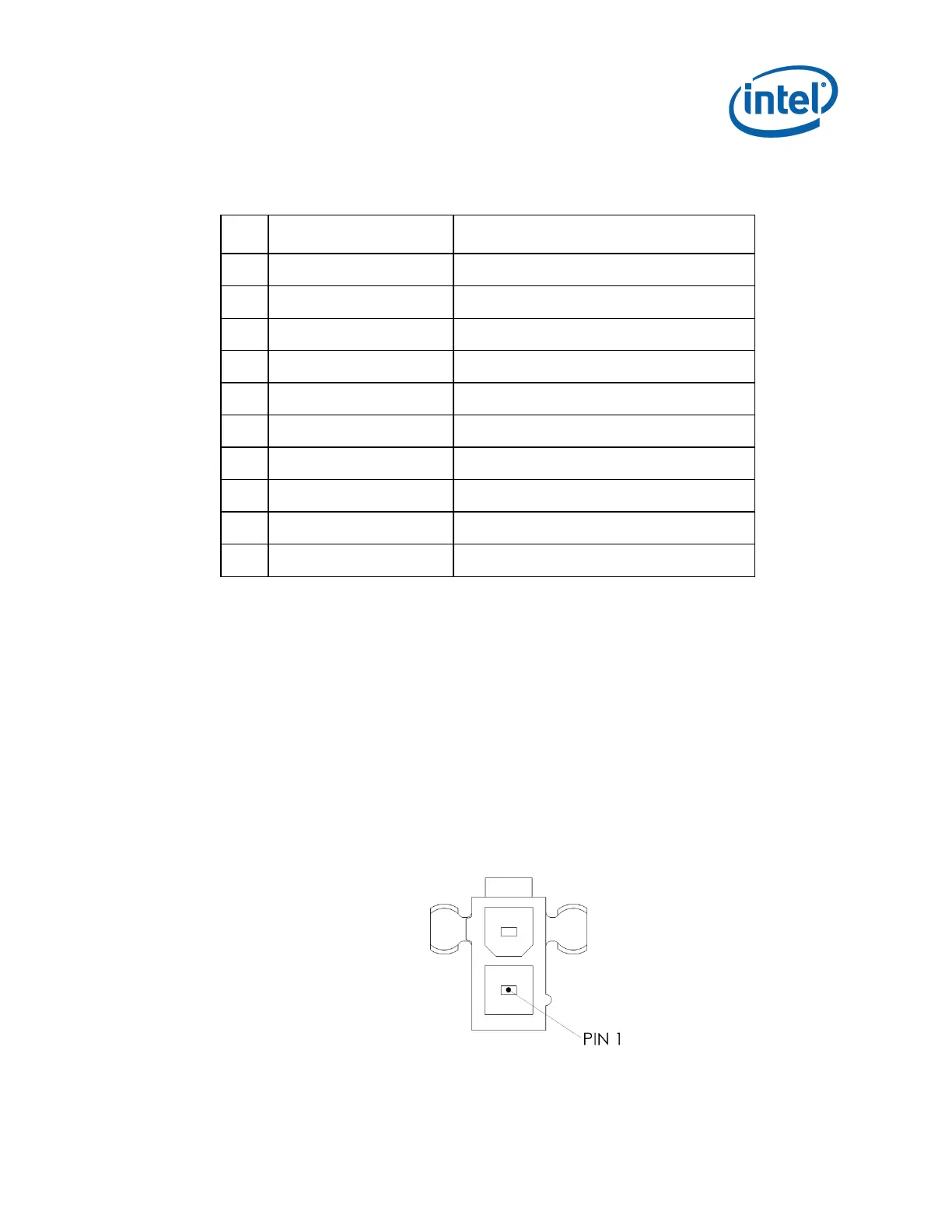
2.7 Internal Power Input
19V internal power input connector: 1x2 shrouded with latch, 9[A] minimum current
rating (part number reference: Molex* 5566-2, or equivalent)
Mating plug reference part number: Molex 5557-02R, or equivalent
See chapter 4 for additional information on power.
Figure 2-14. Internal Power Header

Table of Contents

Questions and Answers:

Question and Answer IconNeed help?

Do you have a question about the Intel Thin Mini-ITX and is the answer not in the manual?

Intel Thin Mini-ITX Specifications

General IconGeneral
BrandIntel
ModelThin Mini-ITX
CategoryMotherboard
LanguageEnglish

Related product manuals