Mechanical
44 Thin Mini-ITX Based PC System Design Guide
5 Mechanical
5.1 CPU Mechanicals
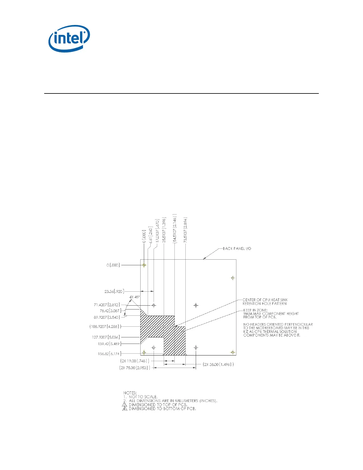
Figure 5-1 specifies the required location of the CPU heat sink retention hole pattern,
based on the standard CPU heat sink retention hole pattern specified in the [Sandy
Bridge/Ivy Bridge] Desktop Processor and LGA1155 Socket Thermal Mechanical
Specifications and Design Guidelines (TMSDG). Additionally, keep-in zones are added
which are intended to support heat pipe routing away from the CPU. CPU keep in
zones in this document are in addition to those specified in the TMSDG and the Mini-
ITX Addendum Version 2.0 to the microATX Motherboard Interface Specification
Version 1.2. Supporting these requirements helps ensure compatibility between
chassis, motherboards, and standardized Thin Mini-ITX thermal solutions such as
Intel’s reference thermal solution in Chapter 6. (Note: this does not apply to Atom
based boards.)
Figure 5-1. CPU Location and Additional Keep In Zones