Thin Mini-ITX Internal Electrical Interfaces
Thin Mini-ITX Based PC System Design Guide 23
Table 2-7. Internal Stereo Speakers Header Pin-Out
Analog front left (differential negative)
Analog front left (differential positive)
Analog front right (differential positive)
Analog front right (differential negative)
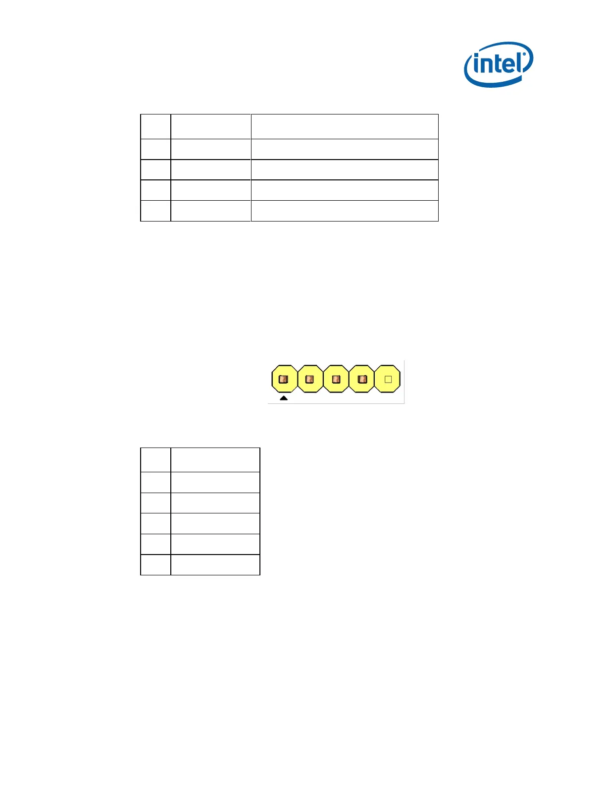
2.3.3 Digital Microphone
A digital microphone (DMIC) can be supported through the below pinout and header.
DMIC MB Header: 1x5, 2.54mm pitch, keyed at pin 5. The header and the mating
DMIC cable connector shall be yellow.
Figure 2-7. DMIC MB Header
Table 2-8. DMIC Header Pin-Out