Thin Mini-ITX Internal Electrical Interfaces
22 Thin Mini-ITX Based PC System Design Guide
Analog Port 1 - Right channel (Microphone)
Active low signal that signals BIOS that an Intel® HD Audio dongle
is connected to the analog header. PRESENCE# = 0 when an
Intel® HD Audio dongle is connected.
Analog Port 2 - Right channel (Headphone)
Jack detection return for front panel (JACK1)
Jack detection sense line from the Intel® HD Audio CODEC jack
detection resistor network
Analog Port 2 - Left channel (Headphone)
Jack detection return for front panel (JACK2)
2.3.2 Internal Stereo Speakers
The R/L (4 ohm) speakers must support 3W and be connected to a R/L audio header
on the motherboard. If subwoofer support is required, then the low pass filtering and
amplification would be with the amp speaker.
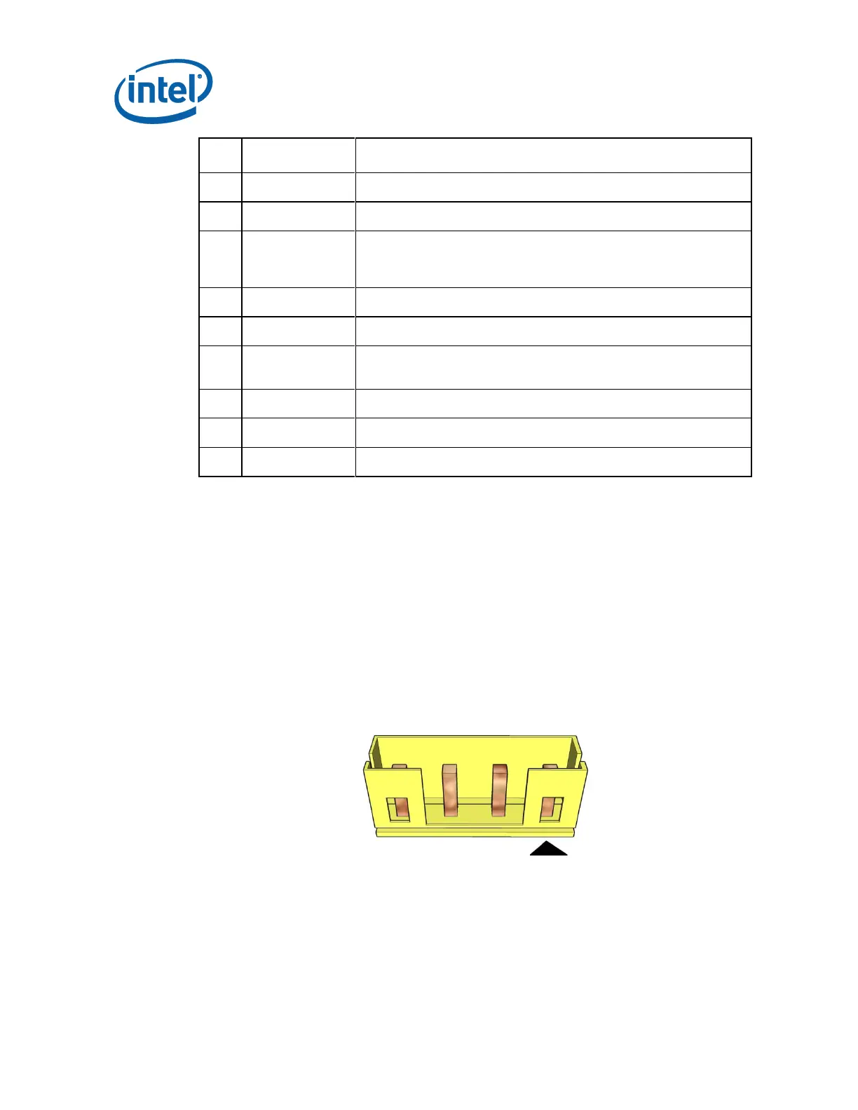
Internal stereo speakers header: 1x4, 2.00mm pitch (part number reference: JS*-
1125-04, or equivalent)
Mating plug reference part number: JWT* A2001H02-4P, or equivalent
Figure 2-6. Internal Stereo Speakers Header