11
Section 1.2
Theory of Operation
Section Overview
This section will cover the circuit operation for the IB series drives.
! Circuit Operation.
! Output Wave Sequences.
! Timing.
Circuit Operation
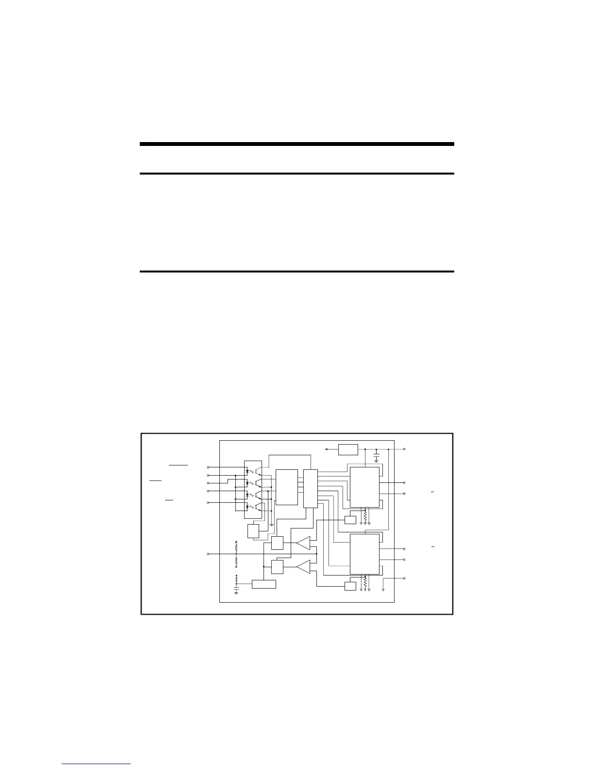
The IB series drives are bipolar chopping stepper motor drives. They
receive step clock, direction and mode signals from the system controller
and generate constant phase currents which are adjustable in magnitude.
The principal functions are: a translator which generates the motor phase
sequences, a dual PWM chopper circuit which regulates the current in the
motor windings and a power stage to drive the motor. The translator
generates three different sequences selected by the half/full step input.
These are normal (two phases energized), wave drive (one phase energized)
Figure 1.2.1: IB Series Block Diagram
TRANSLATOR
DRIVE
LOGIC
+5 VDC
+5v
REGULATOR
OSCILLATOR
Q
SR
Q
S
R
-
+
-
+
+5 VDC
+5 VDC
Q
C
D
ENABLE PIN 1
LOGIC GROUND PIN 2
HALF / FULL STEP PIN 3
STEP CLOCK PIN 4
CW/CCW PIN 5
CURRENT ADJUST PIN 6
FILTER
FILTER
PIN 8 +V
PIN 12 Ø A
PIN 11 Ø A
PIN 10 Ø B
PIN 9 Ø B
PIN 7 GROUND
OUTPUT
BRIDGE
OUTPUT
BRIDGE
 Loading...