27
Basic Connections
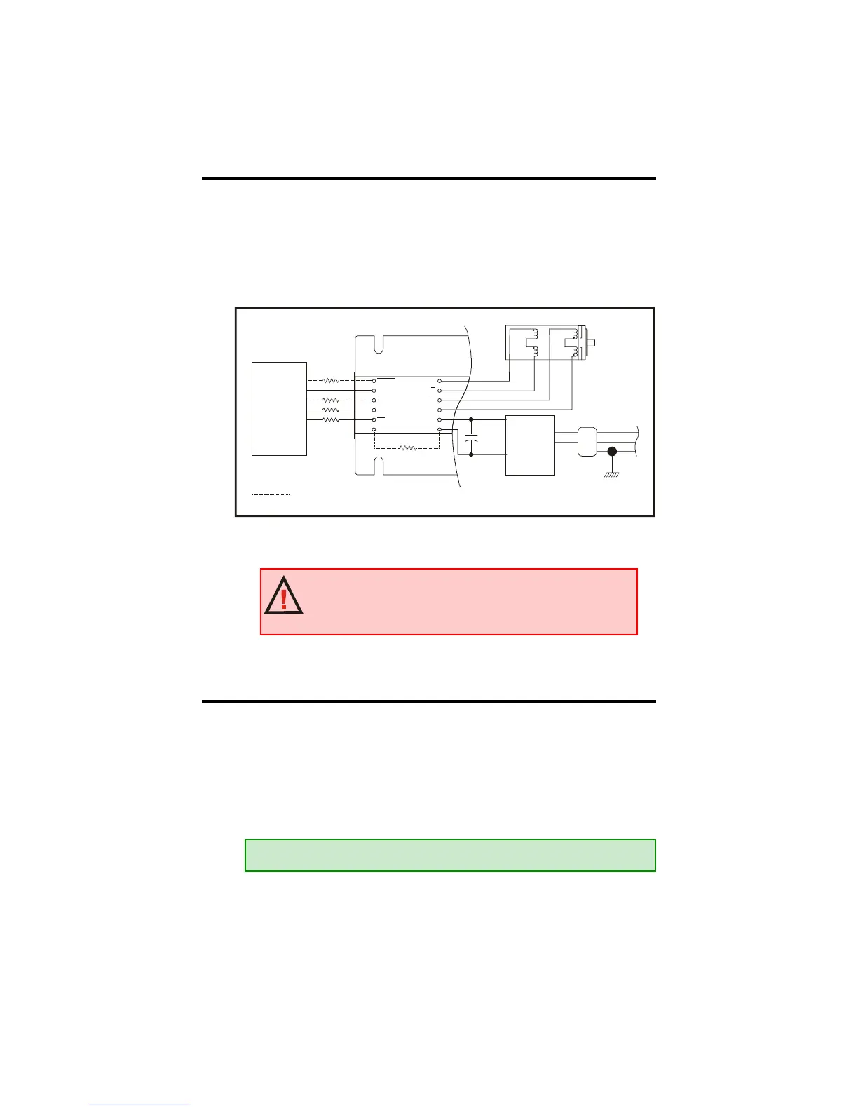
The diagram below illustrates the basic connections required to operate the
IB series driver. The connection of each part is discussed at length in this
section. In order to run the IB drive the following is required: a power
supply, a stepping motor, and a control interface supplying step clock and
direction.
Interfacing Motor Power (+V)
Pins 7 (+V), and 8 (Ground) are used to connect motor DC power to the
IB drive. A low impedance aluminum electrolytic capacitor is required.
The continuous operating voltage of the capacitor should exceed the
maximum supply voltage (+V) as well as any additional voltage caused by
the motor’s back EMF.
Figure 1.5.1: Basic Connections
ENABLE
H
CW
LOGIC
GROUND
/F
STEP
CLOCK
/CCW
CURRENT
ADJUST
PHASE A
PHASE
PHASE B
V+
GROUND
A
PHASE B
POWER
SUPPLY
AC LINE CORD
EARTH
AC LINE
FILTER
HOT
NEUT
+V
GND
CONTROLLER
INTERFACE
OUTPUT
GROUND
OUTPUT
CLOCK
OUTPUT
PIN 1
INPUT
CAPACITOR
DASHED LINE INDICATES THAT THE
CONNECTION OF THIS INPUT IS NOT
REQUIRED FOR DRIVER TO OPERATE.
DRAWNBY JA
WARNING! A current limiting resistor or recommended
interface is required in series with the logic inputs! Use of
these inputs without this resistor or recommended interface
will result in damage to the drive!
EXAMPLE: 5.2A (Peak Output Current)@ 70VDC X 150µF = 780µF 100V
 Loading...