63
Appendix A
OPT140
Optional Interface Board
The OPT140 adds such features to the IB series
drive as:
! A Removable Screw Terminal Interface.
! Isolated Current Reduction.
! 470Ω Pull-up Resistors on Logic Inputs.
! Input Capacitor.
Determining the Resistor Values
Setting the Output Current
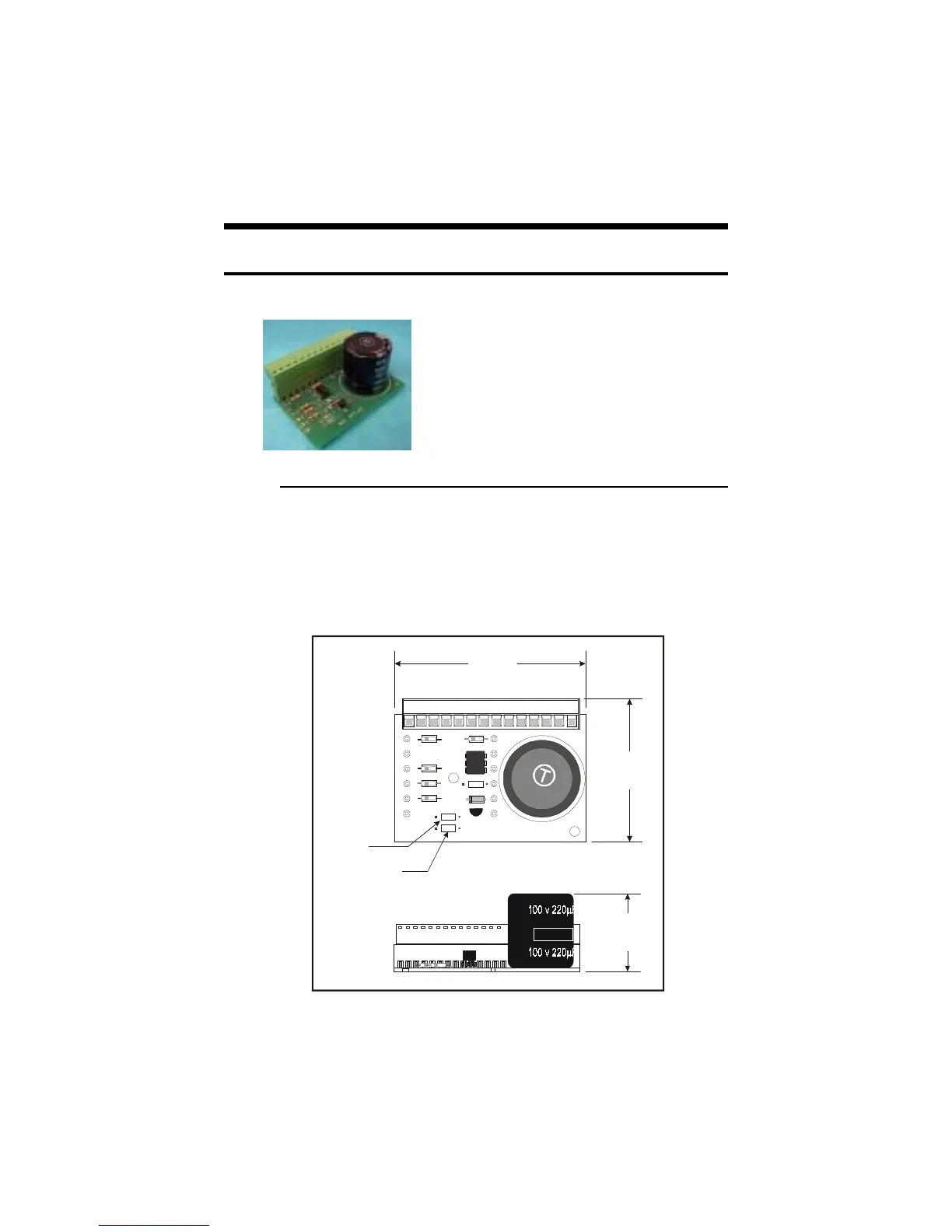
To set the output current on the IB series drive using the OPT140 board
you will need to place R4 (See Figure A.1 below for resistor location). The
value resistor needed will match the resistor table for the model IB drive
you purchased.
Figure A.1: OPT-140 Dimensions
D
C
4N25
4315TK19
R5
R1
R4
IMS OPT140
Q1
P1
12
3
4
56
7
8910
11 12
13
14
2.26
57.5
3.00
(76.2)
1.28
32.5
Current
Adjust
Reduction
Adjust
 Loading...