REV. 07.17.2003
4
Table 4: Recommended Input Current Limiting Resistor Values
srotsiseRgnitimiLtnerruCtupnIdetalosI
ylppuSotpO
)CDV+(
eulaVrotsiseR
)%5smhO(
eulaVrotsiseR
)%1smhO(
5--
01 086 186
2100010001
51 0031 0031
4200720762
A power supply in excess of +5 volts may be used, however a current
limiting resistor MUST be placed in series with the input to limit the input
forward current to the recommended 7 milliamps. At no time can the input
forward current exceed 15 milliamps or damage may occur to the drive.
Interface Methods
The isolated logic inputs may be interfaced to the user’s control system in a
variety of ways. In all cases the inputs are normally in a logic HIGH state when
left floating. For purposes of this manual we will show three interface methods:
1] Switch Interface.
2] Open Collector Interface.
3] TTL Interface.
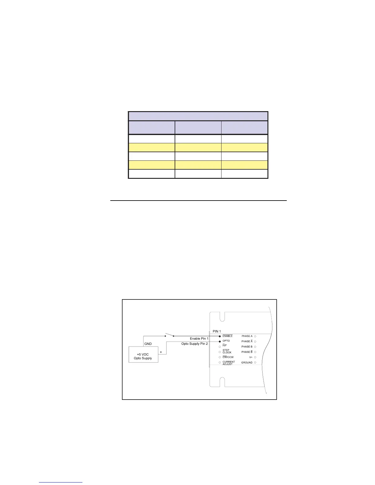
Switch Interface
A switch connected between the input and the opto supply ground will sink the
input. If this method is used a SPST (Single-Pole, Single-Throw) switch works
well for enable and direction. A normally-open momentary switch works well
for reset. Figure 2 illustrates a SPST switch connected to the enable input.
Figure 2: IB Series “S” Version Switch Interface
 Loading...