29
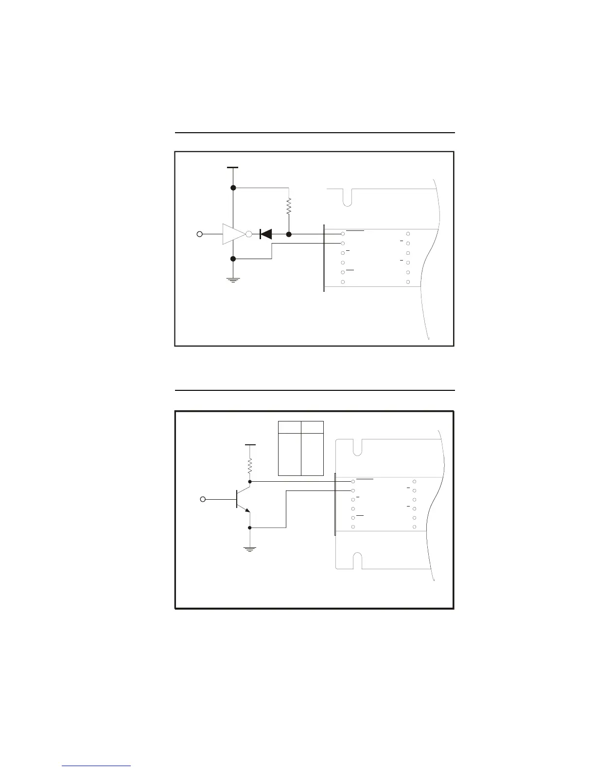
Figure 1.5.3: TTL Interface
Open Collector Interface
Figure 1.5.4: Open Collector Interface
ENABLE
H
CW
LOGIC
GROUND
/F
STEP
CLOCK
/CCW
CURRENT
ADJUST
PHASE A
PHASE
PHASE B
PHASE
V+
GROUND
A
B
PIN 1
DRAWN
BY
A
+5VDC
CONTROLLER
OUTPUT
430
Ω
1N916
OR EQUIV
.
TTL INTERFACE
INTERFACE SHOWN CONNECTED TO
THE ENABLE INPUT, MAY BE USED FOR
THE OTHER LOGIC INPUTS
TTL Interface
ENABLE
H
CW
LOGIC
GROUND
/F
STEP
CLOCK
/CCW
CURRENT
ADJUST
PHASE A
PHASE
PHASE B
PHASE
V+
GROUND
A
B
PIN 1
DRAWNBY
A
+VDC
CONTROLLER
OUTPUT
R
¼ W
OPEN COLLECTOR
INTERFACE
INTERFACE SHOWN CONNECTED TO
THE ENABLE INPUT, MAY BE USED FOR
THE OTHER LOGIC INPUTS
+VDC
5
10
12
15
24
430
1200
1500
2000
3000
R
 Loading...