59
Electrical Specifications
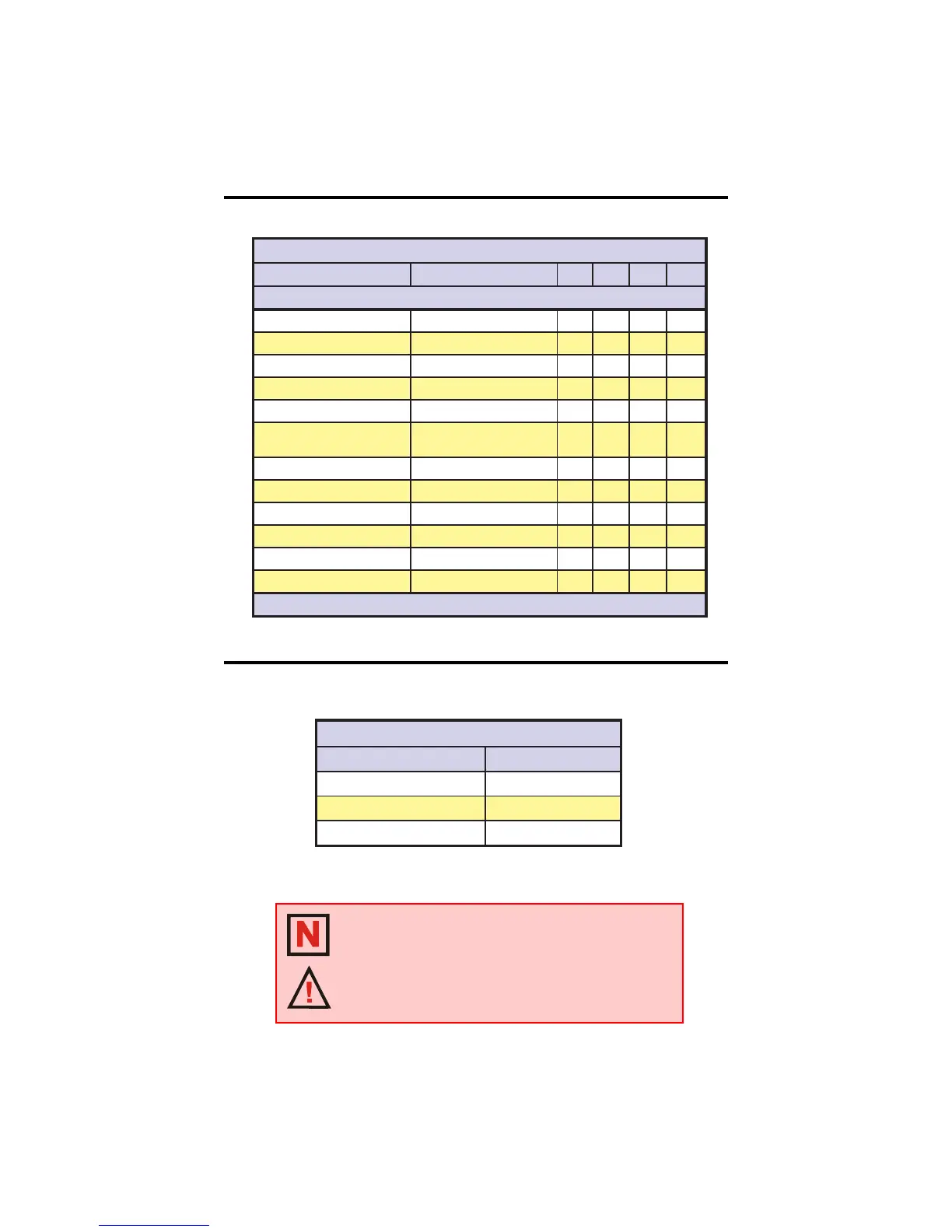
Table 2.5.1: IB1010 Electrical Specifications
Table 2.5.2: IB1010 Thermal Specifications
Thermal Specifications
snoitacificepSlamrehT0101BI
noitacificepS tinU
erutarepmeTtneibmAC°05+ot0
erutarepmeTegarotS C°521+ot04-
erutarepmeTesaCmumixaMC°07
snoitacificepSlacirtcelE0101BI
noitacificepS noitidnoCtseT .niM .pyT .xaM tinU
TnoitidnoCtseTllarevO
A
CDV04=V+,C°52=
)egatloVrotoM(V+42*08V
I
i
tnerruCtupnI 0.9 A
I
Q
tnerruCtnecseiuQgnitaolFstuptuO441Am
R
SD
hgiH I
D
A11-= 711.0 smhO
R
SD
woLI
D
A51=50.077.0smhO
B
RV
nwodkaerBesreveRtupnI
egatloV
5 V
V
F
egatloVdrawroFtupnII
F
Am6.1=5.157.1V
I
F
tnerruCdrawroFtupnI 5 5.7 51 Am
T
KLC
htdiWesluPkcolCpetS3Su
T
S
emiTpu-teS F/H&WCC/WC 2 Su
T
H
emiTdloHF/H&WCC/WC5.5Su
F
C
ycneuqerFnoitatummoC 04 zHk
VsidelbasidstuptuoesahpehthtiwegatlovtupnimumixamehT*
XAM
.%01+
NOTE: Additional cooling may be required to limit case
temperature to 70°C. An optional heat sink, IMS PN H-100,
is available. See Appendix B: Cooling Solutions, for details.
WARNING! The Driver must be mounted to a thermally
conductive surface such as a metal enclosure wall or a
Heat Sink. The Driver must not be operated when resting on
an insulated surface such as wood or acrylic.
 Loading...