65
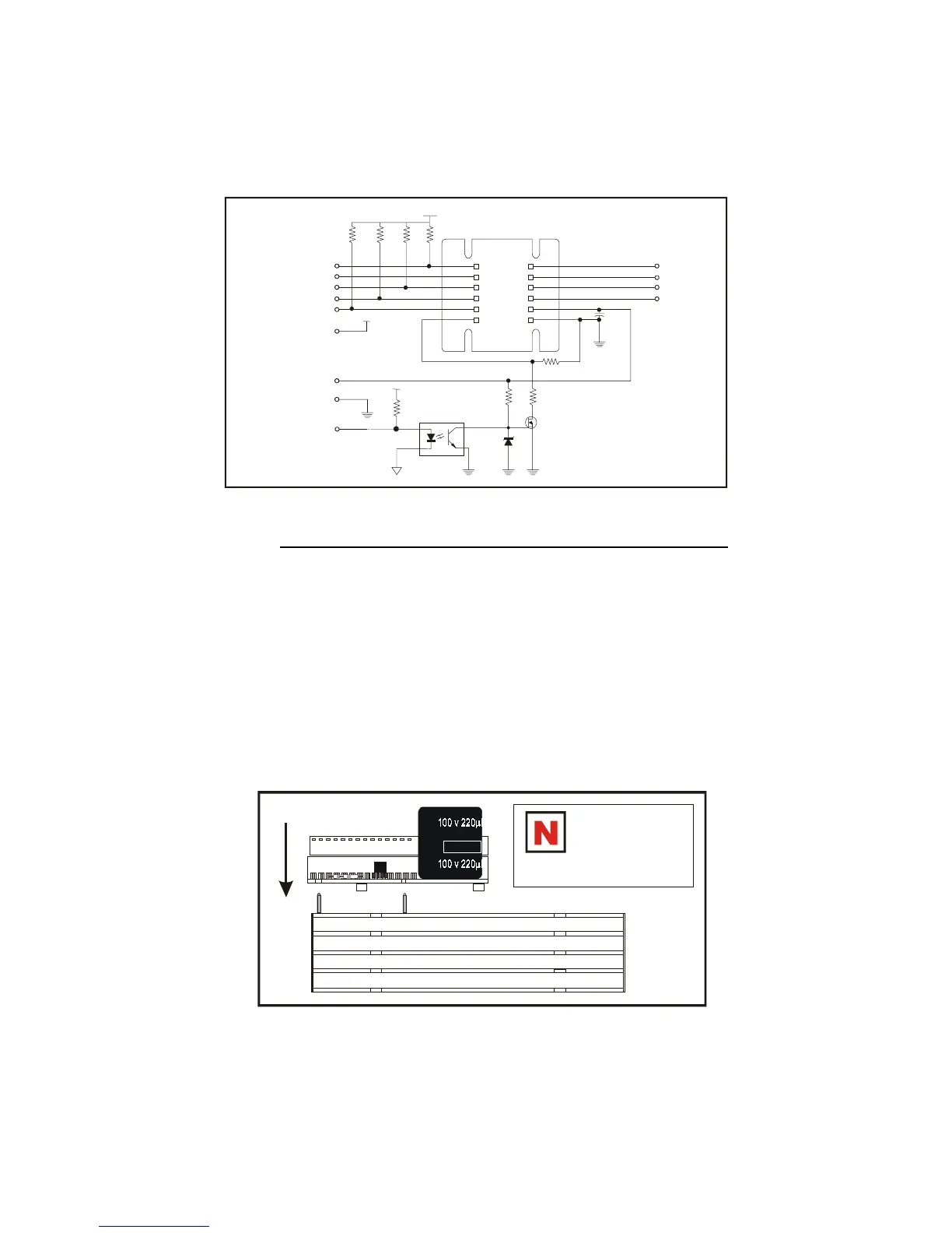
Figure A.3: OPT140 Placement
Mounting the OPT140
The OPT-140 is mounted to the IB drive as shown in figure 2.6.2. The
power, ground and phase output pins (Pins 7-9) of the drive will be next
to the input capacitor.
The pins are then soldered using a recommended solder. Use a recom-
mended solvent for flux removal if required.
Recommended Solders: Recommeded Solvent:
Kester “245” No-clean core solder, Tech Spray “Envorotech 1679”,
Alpha Metals “Telecore Plus” solder, Chemtronics “Flux-off NR 2000”,
Multicore “X39B” No-clean solder, or equivalent.
or equivalent.
Figure A.2: OPT140 Schematic Representation
IB
DRIVER
PIN 1
+5V
+5V
+5V
R8
470
Ω
R7
470
Ω
R6
470
Ω
R2
470
Ω
R3
1k
Ω
C1
2200 F
100V
µ
R5 R1
R4
Z1
10V
Q1
VNO300L
4N25/26
+
PHASE A PIN 9
PHASE A PIN 10
PHASE B PIN 11
PHASE B PIN 12
ENABLE PIN 1
LOGIC GROUND PIN 2
HALF/FULL STEP PIN 4
STEP CLOCK PIN 5
DIRECTION PIN 6
+5VDC PIN 7
POWER GROUND PIN 14
+V PIN 13
CURRENT REDUCTION PIN 8
R1, R4, and R5
should be placed
prior to mounting
the OPT140.
 Loading...