40
Current Adjust Resistor Values
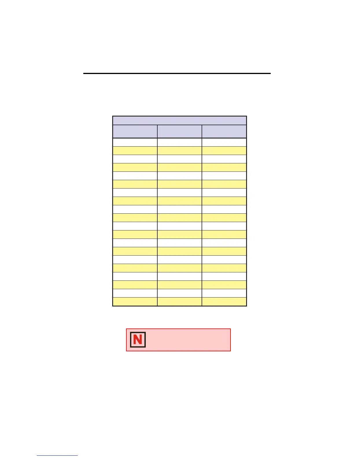
The table below lists the phase currents and their associated adjust resistor
value. Figure 2.1.2 illustrates the reference circuit and contains the equation
for calculating the current adjust resistor value.
Table 2.1.3: IB462 Current Adjust Resistor Values
264BIehtrofseulaVecnerefeRdnarotsiseRtsujdAtnerruC
tnerruCtuptuO
)kaePspmA(
ecnerefeR
)stloV(
eulaVrotsiseR
)%1smhO(
1.050.00.12
2.0 01.0 2.44
3.051.08.96
4.0 02.0 001
5.052.0331
6.0 03.0 961
7.053.0512
8.0 04.0 762
9.054.0423
0.1 05.0 204
1.155.0784
2.1 06.0 406
3.156.0057
4.1 07.0 139
5.157.00121
6.1 08.0 0261
7.158.00622
8.1 09.0 0753
9.159.00867
0.2 00.1 TIUCRICNEPO
NOTE: If a resistor is not placed
between Pins 6 and 7, the drive will
be at full current.
 Loading...