31
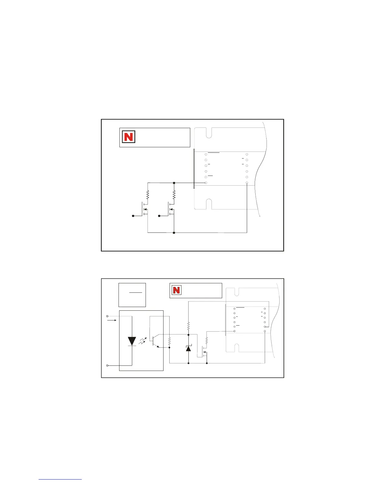
Figure 1.5.7: Switching Phase Currents
Figure 1.5.8: Isolated Switching of Phase Currents
It is possible to switch the current adjust resistor value using the circuit
examples provided in this section. These circuits may be used to switch
from one output current setting to another, or to reduce the current in the
motor windings when the motor is in a locked position. Use of this will
reduce motor and drive heating considerably.
ENABLE
H
CW
LOGIC
GROUND
/F
STEP
CLOCK
/CCW
CURRENT
ADJUST
PHASE A
PHASE
PHASE
PHASE B
V+
GROUND
A
B
PIN 1
DRAWNBY
A
Q1 Q2
+5 VGS WILL TURN ON FETS
Q1 - Q2: VNO300L OR EQUIV.
R 1
ADJ
R 2
ADJ
See Hardware Reference
part for R (current
adjust resistor) values.
adj
ENABLE
H
CW
LOGIC
GROUND
/F
STEP
CLOCK
/CCW
CURRENT
ADJUST
PHASE A
PHASE
PHASE
PHASE B
V+
GROUND
A
B
PIN 1
DRAWN
BY
A
Q1 (VNO300L OR EQUIV.)
R
ADJ
R
+10V
4N25/4N26
I
F
100k
Ω
+V
R =
0.2 x I
F
MIN I = 10mA
F
See Hardware Reference
part for R (current
adjust resistor) values.
adj
 Loading...