REV. 07.17.2003
3
Interfacing and Using the IB Series “S”
Version Isolated Logic Inputs
The IB Series “S” Version has 4 optically isolated logic inputs. These
inputs are isolated to minimize or eliminate electrical noise coupled onto
the drive control signals. Each input is internally pulled-up to the level of
the optocoupler supply and may be connected to sinking outputs on a
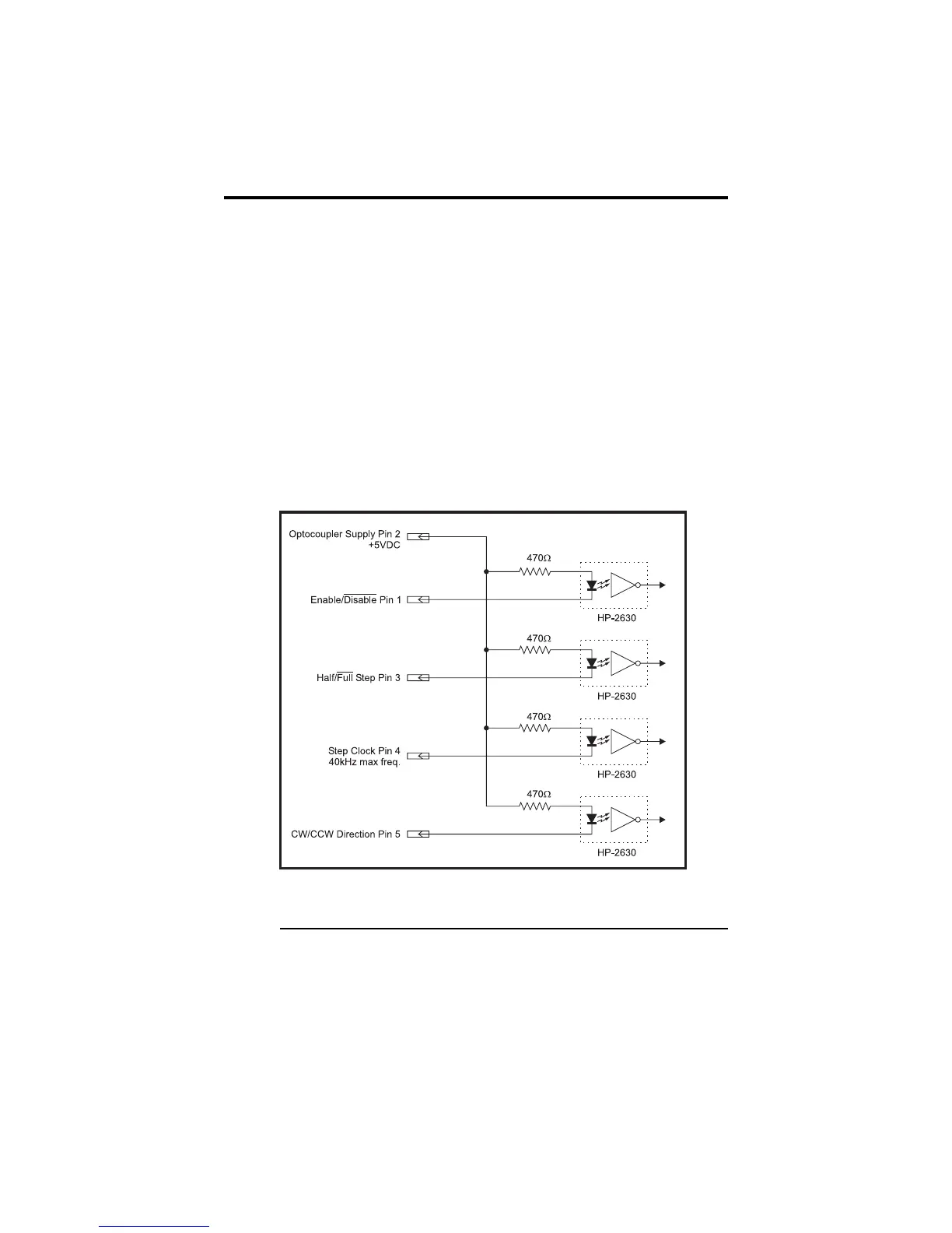
controller such as the IMS LYNX or a PLC. These inputs are:
1] Enable (Pin 1)
2] Half/Full Step (Pin 3)
3] Step Clock (Pin 4)
4] CW/CCW Direction (Pin 5)
Of these inputs only step clock and direction are required to operate the IB
Series “S” Version.
The schematic shown in Figure 1 illustrates the inputs.
Figure 1: Isolated Logic Inputs
Powering the Optocouplers
In order to maintain isolation, the optocouplers must be powered by an
external power supply connected to Pin 2, with the opto supply ground
connected to the ground of the input control circuitry. The logic inputs are
internally limited to allow for a +5VDC power supply.
 Loading...