30
74HC/54HC/74HCT/54HCT Interface
Controlling the Output Current
The IB series drivers are internally configured to run at full current. In
order to lower the output current a resistor must be placed between pin 6
(Current Adjust) and pin 7 (Power Ground). This resistor value will be
different for each model of the IB series. The section pertaining to each
particular model contains a table that lists output current settings and
adjust resistor values.
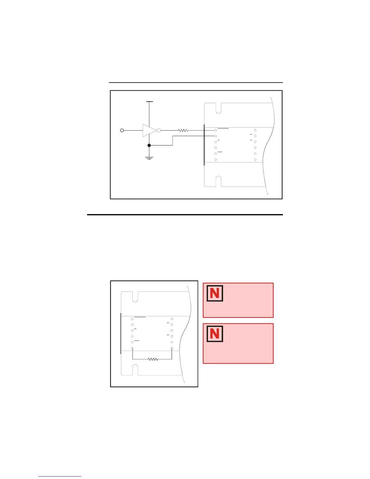
Figure 1.5.5: 74HC/54HC/74HCT/54HCT Interface
Figure 1.5.6: Current Adjust Resistor Placement
ENABLE
H
CW
LOGIC
GROUND
/F
STEP
CLOCK
/CCW
CURRENT
ADJUST
PHASE A
PHASE
PHASE
PHASE B
V+
GROUND
A
B
PIN 1
DRAWNBY
A
+5VDC
CONTROLLER
OUTPUT
430
¼ W
Ω
74HC/54HC/74HCT/54HCT
INTERFACE
INTERFACE SHOWN CONNECTED TO
THE ENABLE INPUT, MAY BE USED FOR
THE OTHER LOGIC INPUTS
ENABLE
H
CW
LOGIC
GROUND
/F
STEP
CLOCK
/CCW
CURRENT
ADJUST
PHASE A
PHASE
PHASE B
PHASE
V+
GROUND
A
B
PIN 1
DRAWNBY
A
CURRENT ADJUST
RESISTOR
NOTE: See the
section in Part II of
this document
pertaining to the
model IB drive purchased for
resistor value tables.
NOTE: If a resistor
is not placed
between Pins 6
and 7, the drive
will be at full current.
 Loading...