REV. 07.17.2003
5
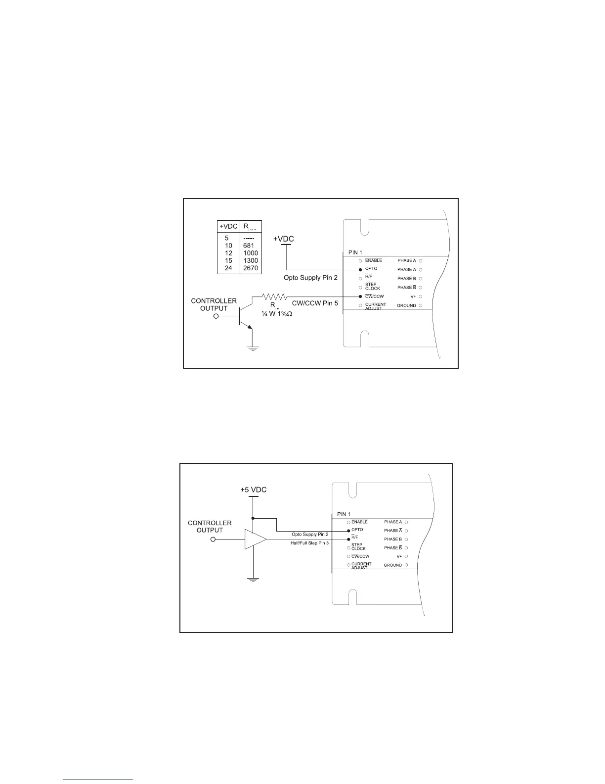
Open Collector Interface
Figure 3 shows an open collector interface connected to the reset input. This
interface method may be used with any of the logic inputs. Remember that a
current limiting resistor is required if an opto supply voltage greater than +5
VDC is used.
Figure 3: IB Series “S” Version Open Collector Interface
TTL Interface
Figure 4 shows a TTL device connected to the enable input. This interface
method may be used with any of the logic inputs.
Figure 4: IB Series “S” Version TTL Interface
 Loading...