User Manual
910.00382.0001 May 2018
18
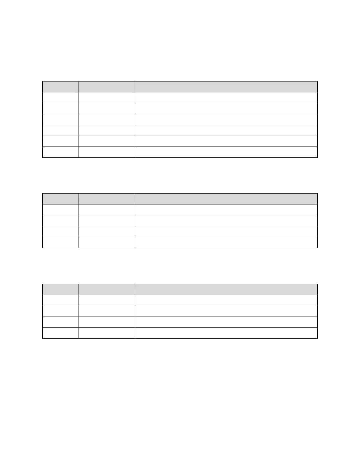
2.3.8 Devices Connector
Redundant terminals are provided for ease of use, for daisy chaining RS-485 where the CAM-5 is not the
last device on the network. Where it is the last device, a ½ Watt 120 Ohm resistor should be placed
between one Data+ and Data–.
Negative Input for Modbus RTU (RS485)
Redundant Negative Input for Modbus RTU (RS485)
Positive Input for Modbus RTU (RS485)
Redundant Positive Input for Modbus RTU (RS485)
Common input for Modbus RTU (RS485)
Redundant Common input for Modbus RTU (RS485)
2.3.9 SMA (RF) Connectors
Air Interface Radio Frequency Port 1
Air Interface Radio Frequency Port 2
Air Interface Radio Frequency Port 3
Air Interface Radio Frequency Port 4
2.3.10 Humidity Sensor Connector
Humidity Cable Power Input from Humidity Sensor
Humidity Cable DATA Input from Humidity Sensor
Humidity Cable Clock Input from Humidity Sensor
Humidity Cable Common Input from Humidity Sensor

 Loading...