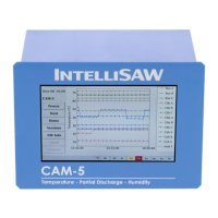
User Manual
910.00382.0001 May 2018
8
1.2 Instructions for Use
The CAM-5 is intended to be installed in the Low Voltage compartment of switchgear or in similar types of
assets. The CAM-5 is intended for use at a maximum altitude of 5km, between -25°C to +70°C (+55°C at
250VAC input) and between 10 - 95% non-condensing relative humidity.
WARNING
THE CAM-5 IS INTENDED ONLY FOR INSTALLATION IN LOW VOLTAGE CONTROL
COMPARTMENTS.
ONLY SENSORS AND AIR INTERFACES ARE INTENDED FOR INSTALLATION IN MEDIUM / HIGH
VOLTAGE COMPARTMENTS.
ONLY WIRELESS SENSORS ARE INTENDED FOR CONTACT WITH ENERGIZED CONDUCTORS
ABOVE 300VRMS.
Failure to follow the instructions given can result in death or serious injury
1.3 System Inputs and Outputs
The maximum system inputs and outputs are as follows:
12 SAW wireless temp sensors
Communications:
Modbus RTU (SCADA)
2
Modbus TCP
DNP3
IEC61850
Email alarms
3
SMS alarms
4
4 air interfaces (TMP or TPD)
8 humidity sensors (series connected)
Power: 100 to 250V AC 50/60 Hz (20W)
120 to 250V DC
1
Alarms: 6 Form C (NO / NC) relays with a
shared common (COM)
MODBUS RTU output requires a non-standard model with RS485 communications card.
Email alarms require connectivity to a user-supplied SMTP server and valid email account for sending data.
SMS is only supported via a compatible cellular gateway device with a user-supplied SIM card and plan.

 Loading...