User Manual
May 2018 910.00382.0001
31
3.5 Alarm Wiring
Connector is shipped with system option
WARNING
ALARM CABLES SHALL NOT BE ROUTED IN COMPARTMENTS WITH CONDUCTORS
EXCEEDING 300V
AC
. FAILURE TO MAINTAIN THIS SPACING CAN RESULT IN ARC FLASH,
PROPERTY DAMAGE, PERSONAL INJURY, AND LOSS OF LIFE.
Failure to follow the instructions given can result in death or serious injury
IMPORTANT
ALARM OUTPUTS ARE FOR INDICATION ONLY AND ARE NOT INTENDED FOR CONTROLLING
THE ELECTRICAL PROCESS.
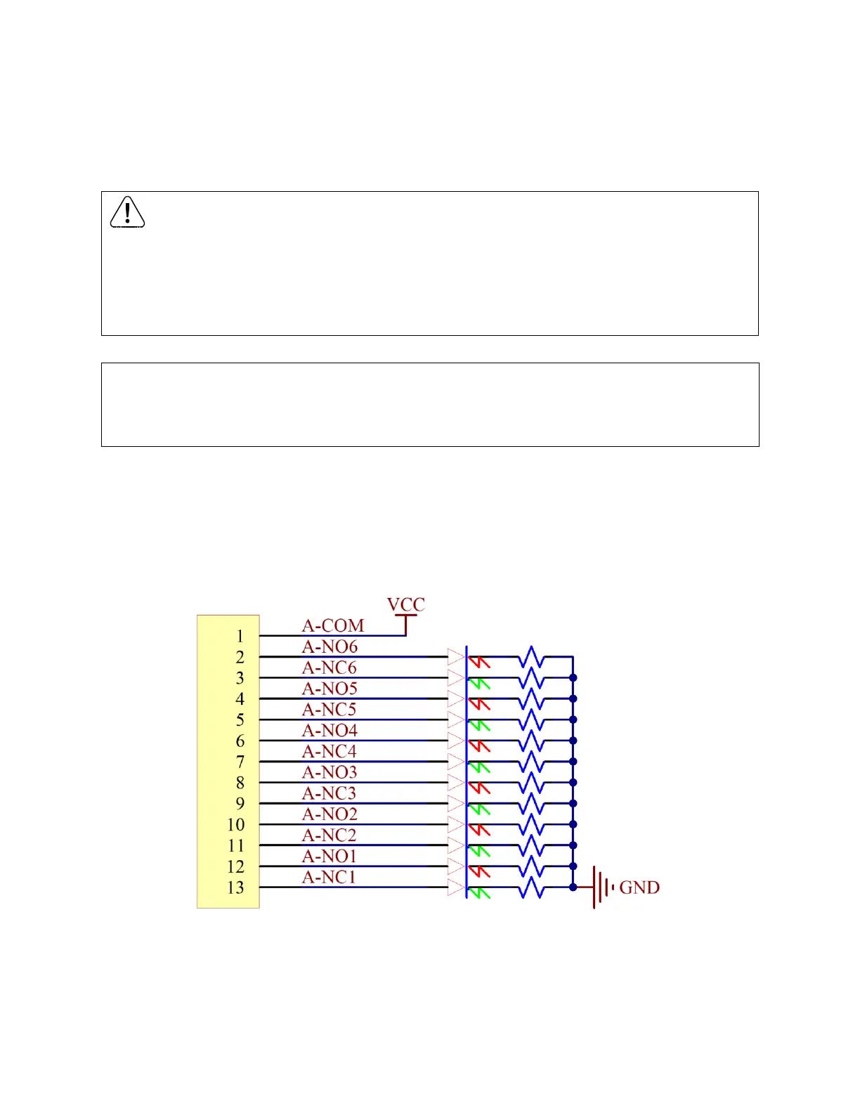
Six (6) Form C Dry Contact Relays are provided with the Alarm option. A common signal is applied to A-
COM, and, at normal state, will be connected to the NC contact for each relay. When a relay closes on a
positive alarm trigger, the common signal will propagate through the NO contact after breaking the NC
connection.
Figure 15: Relay wiring with high side common.

 Loading...