User Manual
May 2018 910.00382.0001
25
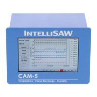
Figure 11: IntelliSAW CAM-5 Power Wiring
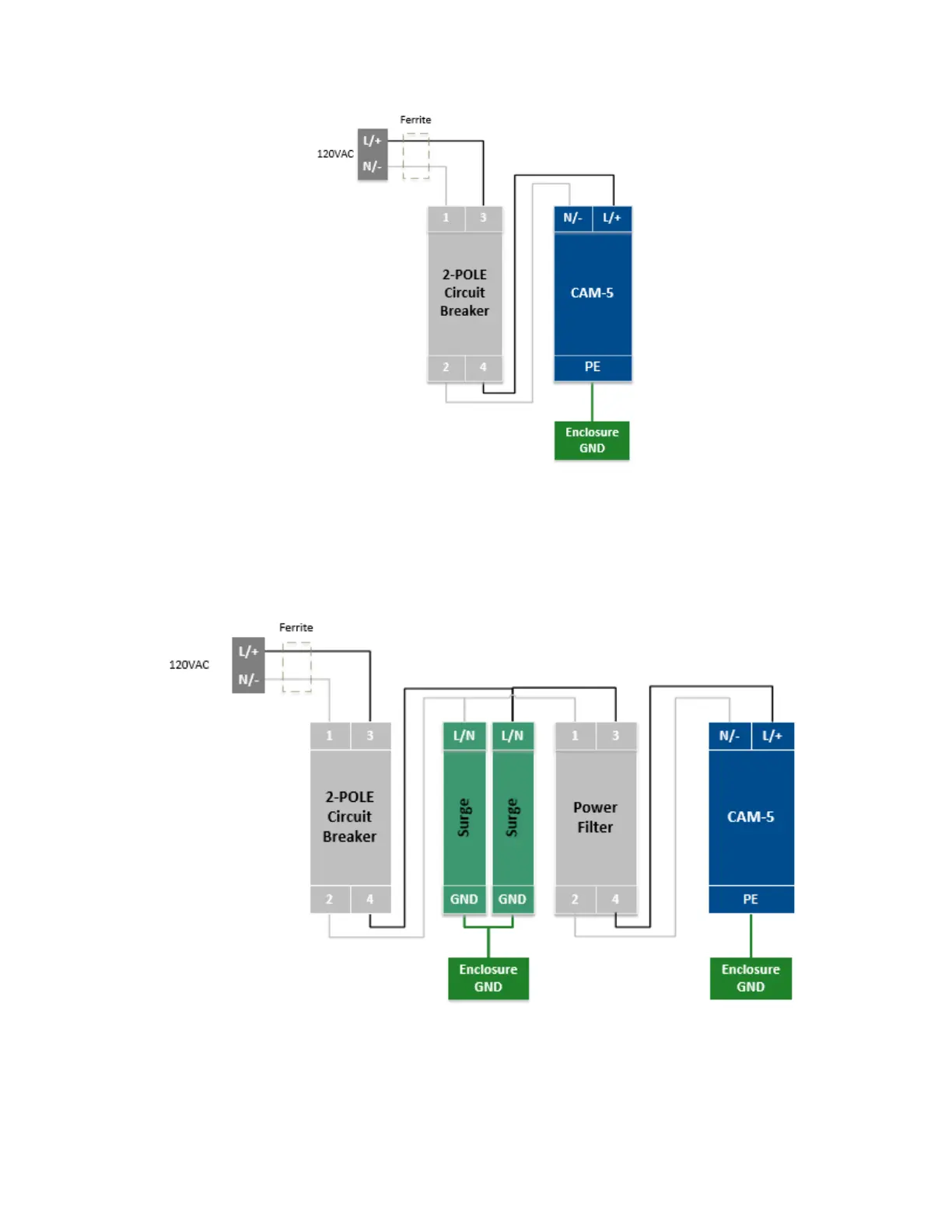
The following block diagram adds external AC line filters and surge arrestors for enhanced EMC
protection. Line filters will reduce conducted signals that may show as false positives for UHF partial
discharge measurements. The additional surge arrestors may be desired for 250Vac type 3 or 4
interfaces, as defined in IEC61000-6-5, or if EFT and surge voltages greater than 4KV or surges with
abnormally high occurrence are anticipated.
Figure 12: Power Wiring With Surge Suppression And Power Line Filtering
 Loading...