Product information
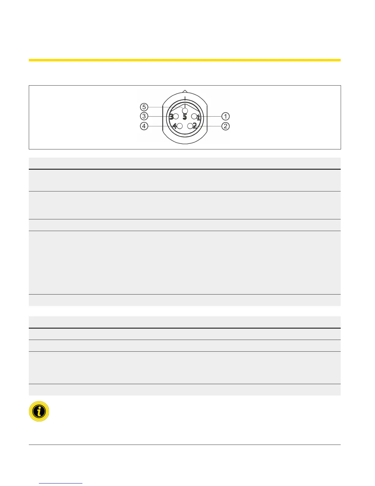
3.8 RollerDrive connector
Pin Colour Function Value
1 Brown Input of the power supply (+) Rated voltage: 24 V DC
Voltage range: 18 to 28 V DC
2 White Input of the rotational direction as
seen from the end of the cable of the
RollerDrive
"Low" = anti-clockwise
"High" = clockwise
3 Blue Earth for power supply and signal (-) Earth
4 Black Error output Open collector
U
CESAT
= 0.5 V DC at I
C
= 5 mA
U
MAX
= 30 V DC
I
CMAX
= 5 mA
Error: "Low" signal
No error: "High" signal
5 Grey Analogue speed/start signal See table below
Analogue speed/start signal (pin 5)
Voltage range 0 to 24 V DC
Stop (zero motion hold) 0 to 2.3 V DC
Speed 2.3 V DC to 10 V DC
2.3 V = minimum speed
10 V = maximum speed
Max. speed 10 V DC to 24 V DC
The conveyor speed results from the gear ratio and the voltage rating of the analogue speed signal.