Version 3.00 | Optidrive P2 User Guide | 23www.invertekdrives.com
4.6. Motor Connection
The drive inherently produces fast switching of the output voltage (PWM) to the motor compared to the mains supply, for motors
which have been wound for operation with a variable speed drive then there is no preventative measures required, however if the
quality of insulation is unknown then the motor manufacturer should be consulted and preventative measures may be required.
The motor should be connected to the Optidrive U, V, and W terminals using a suitable 3 or 4 core cable. Where a 3 core cable
is utilised, with the shield operating as an earth conductor, the shield must have a cross sectional area at least equal to the phase
conductors when they are made from the same material. Where a 4 core cable is utilised, the earth conductor must be of at least
equal cross sectional area and manufactured from the same material as the phase conductors.
The motor earth must be connected to one of the Optidrive earth terminals to provide a low impedance path for common mode
leakage current to return to the drive. This is best achieved in practice by using a cable with suitable shielding which provides a low
impedance path at high frequencies, and ensuring correct, low impedance earth bonding of the motor cable at both ends. For further
information, refer to section 4.13. EMC Compliant Installation on page 26.
4.7. Motor Terminal Box Connections
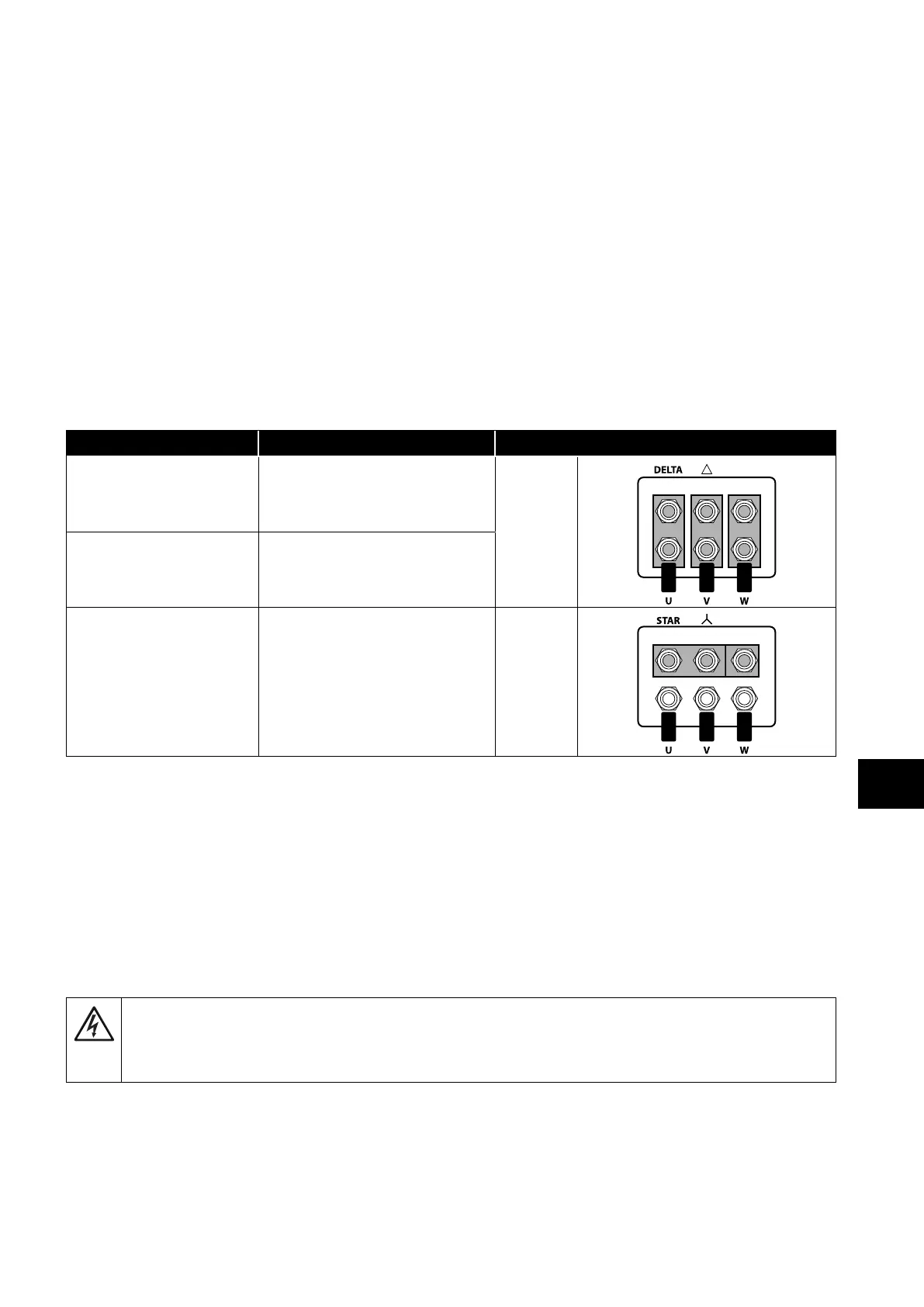
Most general purpose motors are wound for operation on dual voltage supplies. This is indicated on the nameplate of the motor. This
operational voltage is normally selected when installing the motor by selecting either STAR or DELTA connection. STAR always gives
the higher of the two voltage ratings.
Incoming Supply Voltage Motor Nameplate Voltages Connection
230 230 / 400
Delta
400 400 / 690
400 230 / 400 Star
4.8. Connecting a Brake Resistor
Optidrive P2 units feature an internal brake transistor, fitted as standard for all models. The brake resistor should be connected to the
DC+ and BR terminals of the drive. These terminals may be ??????
The brake transistor is enabled using P1-05 (Refer to section 8.1. Parameter Group 2 - Extended Parameters on page 44 for further
information).
Software protection against brake resistor overload is carried out within the drive. For correct protection of the brake resistor, the
following settings are required:
Set P1-14 = 201.
Enter the resistance of the brake resistor in P6-19 (Ohms).
Enter the power of the brake resistor in P6-20 (kW).
The voltage level at these terminals may exceed 800VDC.
Stored charge may be present after disconnecting the mains power.
Allow a minimum of 5 minutes discharge after power off before attempting any connection to these
terminals.
4.9. Control Terminal Wiring
All analog signal cables should be suitably shielded. Twisted pair cables are recommended.
Power and Control Signal cables should be routed separately where possible, and must not be routed parallel to each other.
Signal levels of different voltages e.g. 24 Volt DC and 110 Volt AC, should not be routed in the same cable.
Maximum control terminal tightening torque is 0.5Nm.
Control Cable entry conductor size: 0.05 – 2.5mm
2
/ 30 – 12 AWG.
4
Electrical Installation

 Loading...
