32 | Optidrive P2 User Guide | Version 3.00 www.invertekdrives.com
5
Installation & Operating Instructions
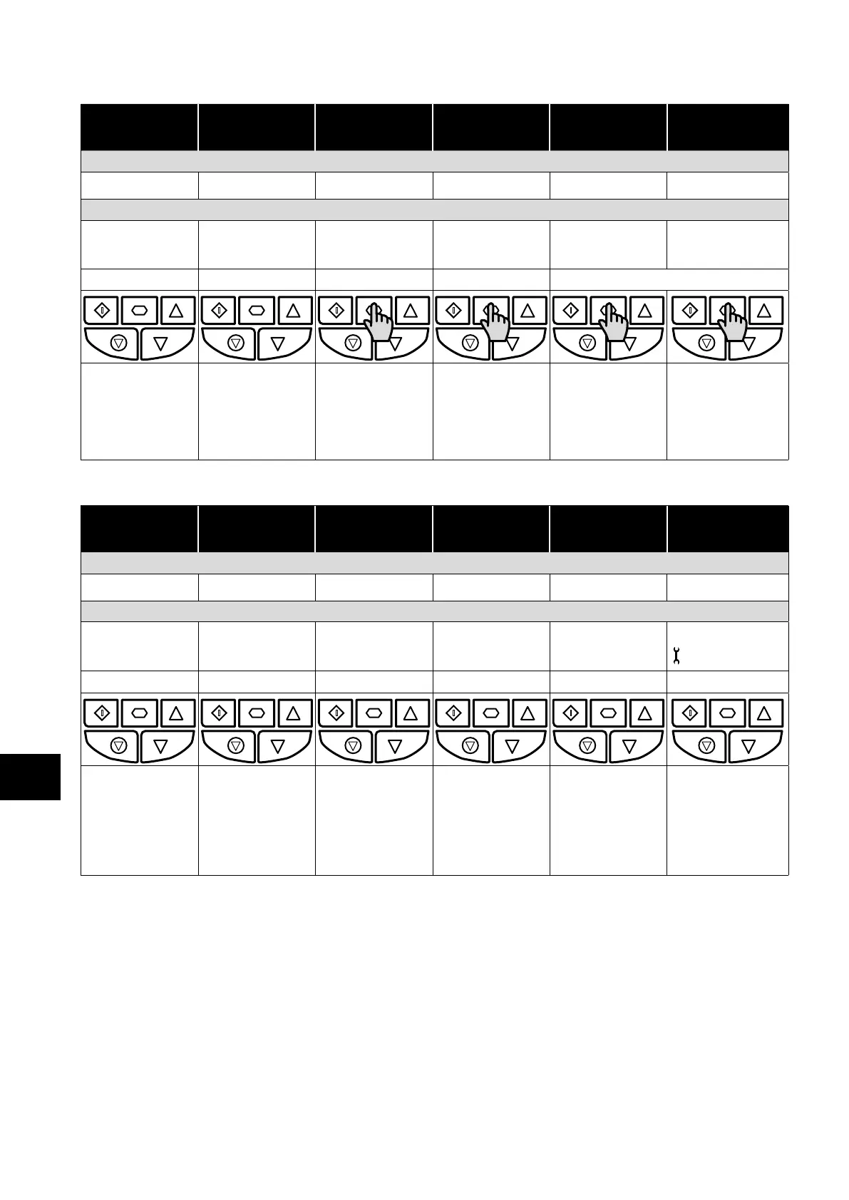
5.3.1. Operating Displays
Inhibit /
STO Active
Drive Stopped Drive Running
Output Frequency
Display
Drive Running
Output Current
Display
Drive Running
Motor Power
Display
Drive Running
Motor Speed
Display
LED Display :
.
.
.
OLED Display :
P2 01 P2 01
Output Frequency 01
Motor Current 01 Motor Power 01 Motor Speed 01
INHIBIT STOP 23.7Hz 15.3A 6.9kW 718rpm
15 kW 400V 3Ph 15kW 400V 3Ph 15.3A 6.9kW 6.9kW 23.7Hz 23.7Hz 15.3A 23.7Hz 15.3A
Drive Inhibited. The
STO connections are
not made.
Refer to section
4.14.8. Recommended
“STO” Wiring on
page 29.
Drive Stopped /
Disabled.
Drive is enabled
/ running, display
shows the output
frequency (Hz). Press
the Navigate key
to select alternative
displays.
Press the Navigate
key for < 1 second.
The display will show
the motor current
(Amps).
Press the Navigate
key for < 1 second.
The display will show
the motor power
(kW).
If P-10 > 0, pressing
the Navigate key for <
1 second will display
the motor speed
(RPM).
5.4. Additional Display Messages
Auto Tuning in
Progress
External 24VDC
Supply
Overload Switching
Frequency
Reduction
Mains Loss Maintenance
Time Elapsed
LED Display :
Not Indicated Not Indicated Not Indicated
OLED Display :
P2 01 P2 01 P2 01 P2 01 P2 01
Auto-tuning
Ext 24V
OL
23.7Hz
SF
23.7Hz
ML
23.7Hz 23.7Hz
External 24V mode
15.3A 6.9kW 15.3A 6.9kW 15.3A 6.9kW 15.3A 6.9kW
Auto tune in progress.
See parameter P4-02
information in section
8.2.3. Parameter
Group 4 – High
Performance Motor
Control on page
50.
The drive control
board is powered
only from an external
24 Volt source, with
no mains power
applied.
Indicates an
Overload condition.
Output current
exceeds the motor
rated current entered
in Parameter P1-08.
Switching frequency is
reduced, due to high
heatsink temperature.
The incoming mains
power supply has
been disconnected or
is missing.
The user
programmable
maintenance reminder
time has elapsed.
 Loading...

