Version 3.00 | Optidrive P2 User Guide | 49www.invertekdrives.com
8.2. Parameter Group 3 – PID Control
8.2.1. Overview
Optidrive P2 provides an internal PID controller. Parameters for configuration of the PID controller are located together in Group 3.
For simple applications, the user needs to only define the setpoint source (P3-05 to select the source or P3-06 for a fixed setpoint),
feedback source (P3-10) and adjust the P Gain (P3-01), I time (P3-02) and optionally the differential time (P3-03).
The PID operation is uni-directional, and all signals are treated as 0 – 100% to provide a simple, intuitive operating format.
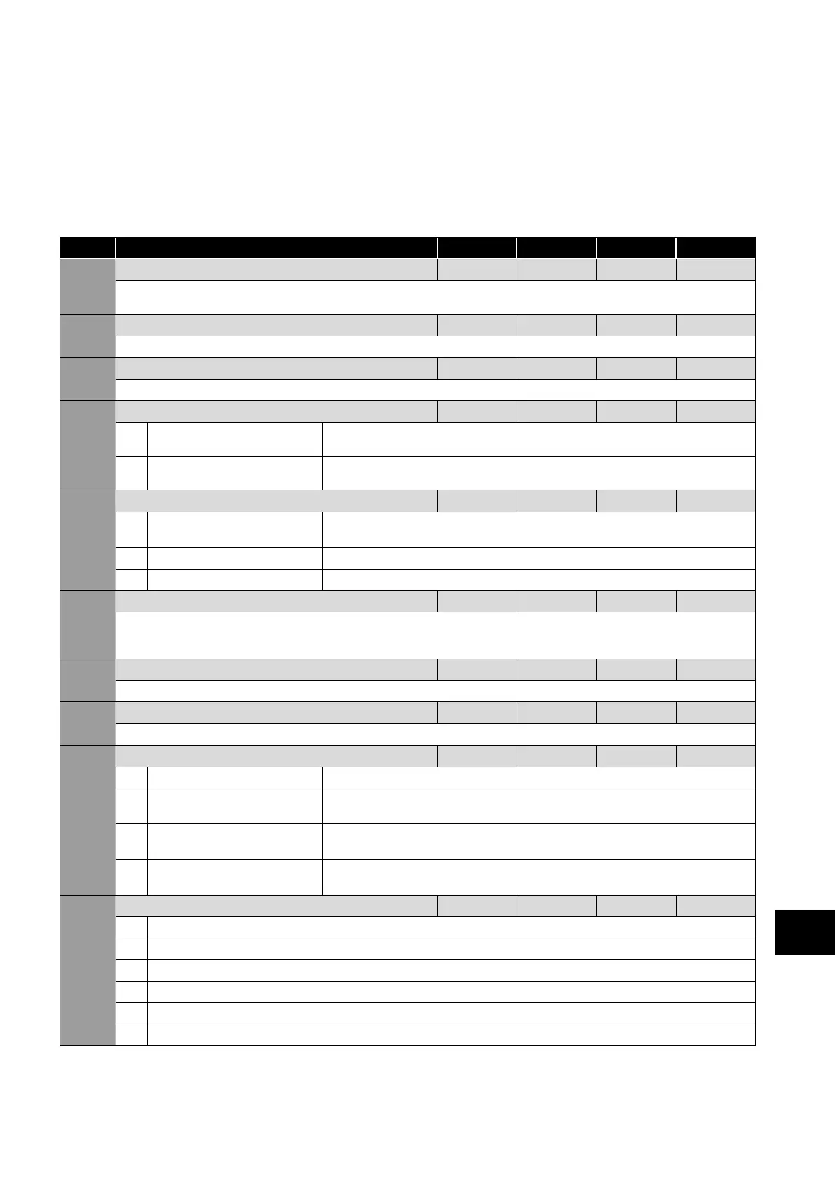
8.2.2. Parameter List
Par Parameter Name Minimum Maximum Default Units
P3-01 PID Proportional Gain 0.1 30.0 1.0 -
PID Controller Proportional Gain. Higher values provide a greater change in the drive output frequency in response to small changes
in the feedback signal. Too high a value can cause instability.
P3-02 PID Integral Time Constant 0.0 30.0 1.0 s
PID Controller Integral Time. Larger values provide a more damped response for systems where the overall process responds slowly.
P3-03 PID Differential Time Constant 0.00 1.00 0.00 s
PID Differential Time Constant.
P3-04 PID Operating Mode 0 1 1 -
0 Direct Operation Use this mode if an increase in the motor speed should result in an increase in the
feedback signal.
1 Inverse Operation Use this mode if an increase in the motor speed should result in a decrease in the
feedback signal.
P3-05 PID Reference (Setpoint) Source Select 0 2 0 -
0 PID Reference (Setpoint)
Source Select
P3-06 is used.
1 Analog Input 1 Setpoint Analog Input 1 as displayed in P0-01 is used.
2 Analog Input 2 Setpoint Analog Input 2 as displayed in P0-02 is used.
P3-06 PID Digital Reference (Setpoint) 0.0 100.0 0.0 %
When P3-05 = 0, this parameter sets the preset digital reference (setpoint) used for the PID Controller. Where the feedback is provided
from a transducer such as a pressure transducer or level measurement, this represents the percentage of the pressure range (e.g. for a 0 –
10 Bar transducer, 4 bar = 40%) or the level.
P3-07 PID Controller Output Upper Limit P3-08 100.0 100.0 %
Limits the maximum value output from the PID controller.
P3-08 PID Controller Output Lower Limit 0.0 P3-07 0.0 %
Limits the minimum output from the PID controller.
P3-09 PID Output Limit Control 0 3 0 -
0 Digital Output Limits The output range of the PID controller is limited by the values of P3-07 & P3-08.
1 Analog Input 1 Provides a
Variable Upper Limit
The output range of the PID controller is limited by the values of P3-08 & the signal
applied to Analog Input 1.
2 Analog Input 1 Provides a
Variable Lower Limit
The output range of the PID controller is limited by the signal applied to Analog Input 1 &
the value of P3-07.
3 PID output Added to
Analog Input 1 Value
The output value from the PID Controller is added to the speed reference applied to the
Analog Input 1.
P3-10 PID Feedback Signal Source Select 0 1 0 -
0 Analog Input 2
1 Analog Input 1
2 Output Current
3 DC Bus Voltage
4 Differential : Analog Input 1 – Analog Input 2
5 Largest Value : Analog Input 1 or Analog Input 2
8
Extended Parameters
 Loading...

