Version 3.00 | Optidrive P2 User Guide | 21www.invertekdrives.com
4
Electrical Installation
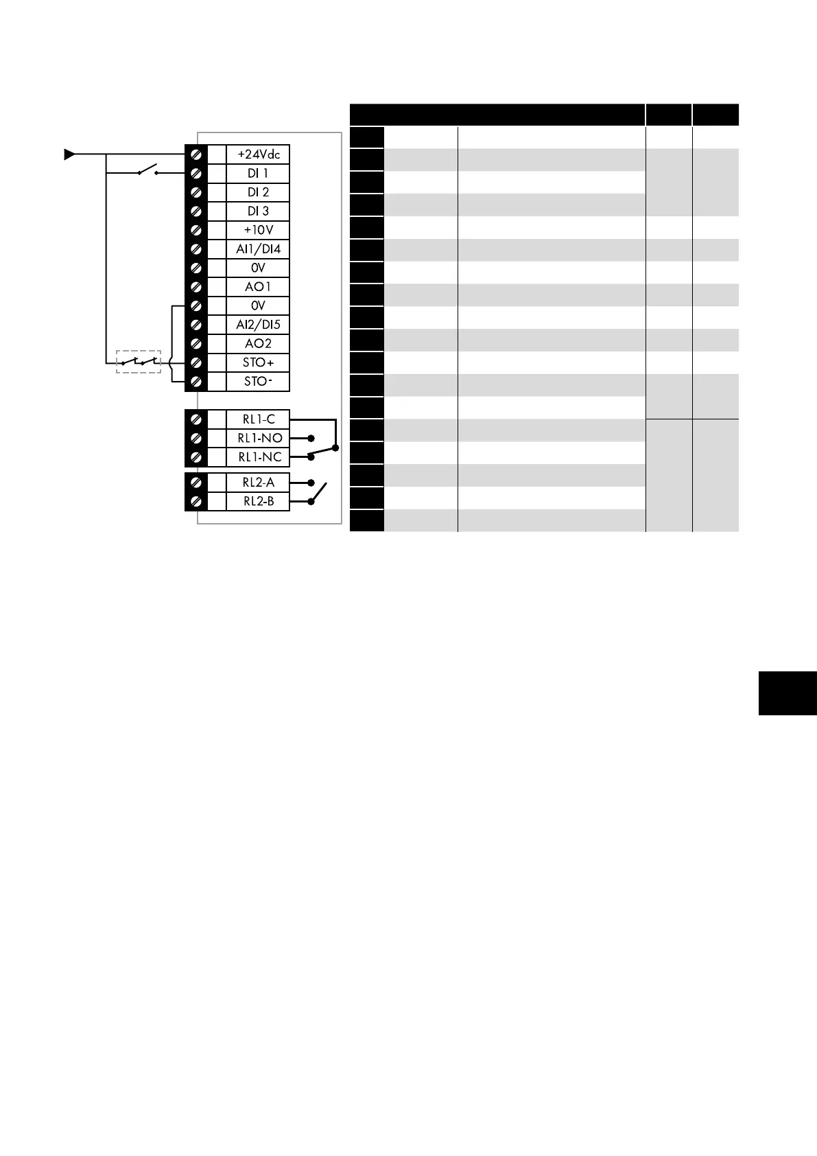
4.1.2. Control Connections
Key Sec. Page
1
2
3
4
5
6
7
8
9
10
11
12
13
14
15
16
17
18
1 +24V 24 Volt DC Input / Output
4.10.1 24
2 DI1 Digital Input 1 (Run Enable)
4.10.2 24
3 DI2 Digital Input 2
4 DI3 Digital Input 3
5 +10V +10Volt DC Output
6 AI1 / DI4 Analog Input 1 / Digital Input 4
4.10.3 24
7 0V 0 Volt Common
8 AO1 Analog Output 1
4.10.4 24
9 0V 0 Volt Common
10 AI2 / DI5 Analog Input 2 / Digital Input 5
4.10.3 24
11 AO2 Analog Output 2
4.10.4 24
12 STO- STO 0 Volt Connection
4 .14 27
13 STO+ STO + 24VDC Connection
14 RL1-C Relay Output 1 Common
4.10.5 24
15 RL1-NO Relay Output 1 Normally Open
16 RL1-NC Relay Output 2 Normally Closed
17 RL2-A Relay Output 2
18 RL2-B Relay Output 2
4.2. Protective Earth (PE) Connection
4.2.1. Grounding Guidelines
Adequate safety earthing must be provided in accordance with local wiring rules and codes of practice. The ground terminal of
each Optidrive should be connected back to the common safety earth bar to maintain touch potentials within safe limits. The ground
terminal of each Optidrive should be individually connected DIRECTLY to the site ground bus bar (through the EMC filter if installed).
Optidrive ground connections should not loop from one drive to another, or to, or from any other equipment. Ground impedance must
conform to local industrial safety regulations and/or electrical codes.
To meet UL regulations, UL approved ring crimp terminals should be used for all ground wiring connections.
The integrity of all ground connections should be checked periodically.
4.2.2. Protective Earth Conductor
The Cross sectional area of the PE Conductor must be at least equal to that of the incoming supply conductors.
4.2.3. Motor Ground
The driven motor must be locally connected to a suitable ground location to maintain touch potentials within safe limits. In addition, the
motor ground must be connected to one of the ground terminals on the drive.
4.2.4. Ground Fault Monitoring
As with all inverters, a leakage current to earth can exist. The Optidrive is designed to produce the minimum possible leakage current
whilst complying with worldwide standards. The level of current is affected by motor cable length and type, the effective switching
frequency, the earth connections used and the type of RFI filter installed. If an ELCB (Earth Leakage Circuit Breaker) is to be used, the
following conditions apply:
A Type B Device must be used.
The device must be suitable for protecting equipment with a DC component in the leakage current.
Individual ELCBs should be used for each Optidrive.
4.2.5. Shield Termination (Cable Screen)
The safety ground terminal provides a grounding point for the motor cable shield. The motor cable shield connected to this terminal
(drive end) should also be connected to the motor frame (motor end). Use a shield terminating or EMI clamp to connect the shield to
the safety ground terminal.

 Loading...
