20 | Optidrive P2 User Guide | Version 3.00 www.invertekdrives.com
4
Electrical Installation
4. Electrical Installation
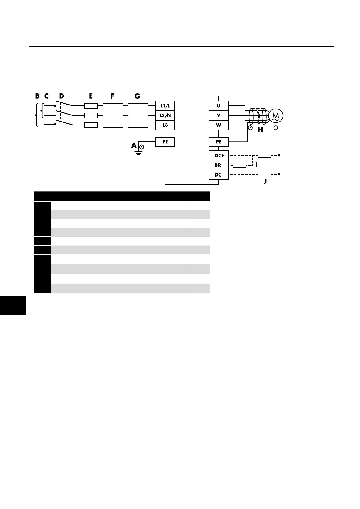
4.1. Connection Diagram
All power terminal locations are marked directly on the product. IP20 Frame Size 2 – 4 units have AC/DC power input located at the
top with the motor and brake resistor connections located at the bottom. All other units have power terminals located at the bottom.
4.1.1. Electrical Power Connections
Key Page
A 4.2. Protective Earth (PE) Connection 21
B 4.3. Incoming Power Connection 22
C 4.3. Incoming Power Connection 22
D External Isolator / Disconnect -
E 4.3.3. Fuse / Circuit Breaker Selection 22
F 4.3.4. Optional Input Choke 22
G 4.13. EMC Compliant Installation 26
H 4.6. Motor Connection 23
I 4.8. Connecting a Brake Resistor 23
J 4.5. Operation with DC Power Supply or Common DC Bus 22

 Loading...
