44 | Optidrive P2 User Guide | Version 3.00 www.invertekdrives.com
8
Extended Parameters
8. Extended Parameters
8.1. Parameter Group 2 - Extended Parameters
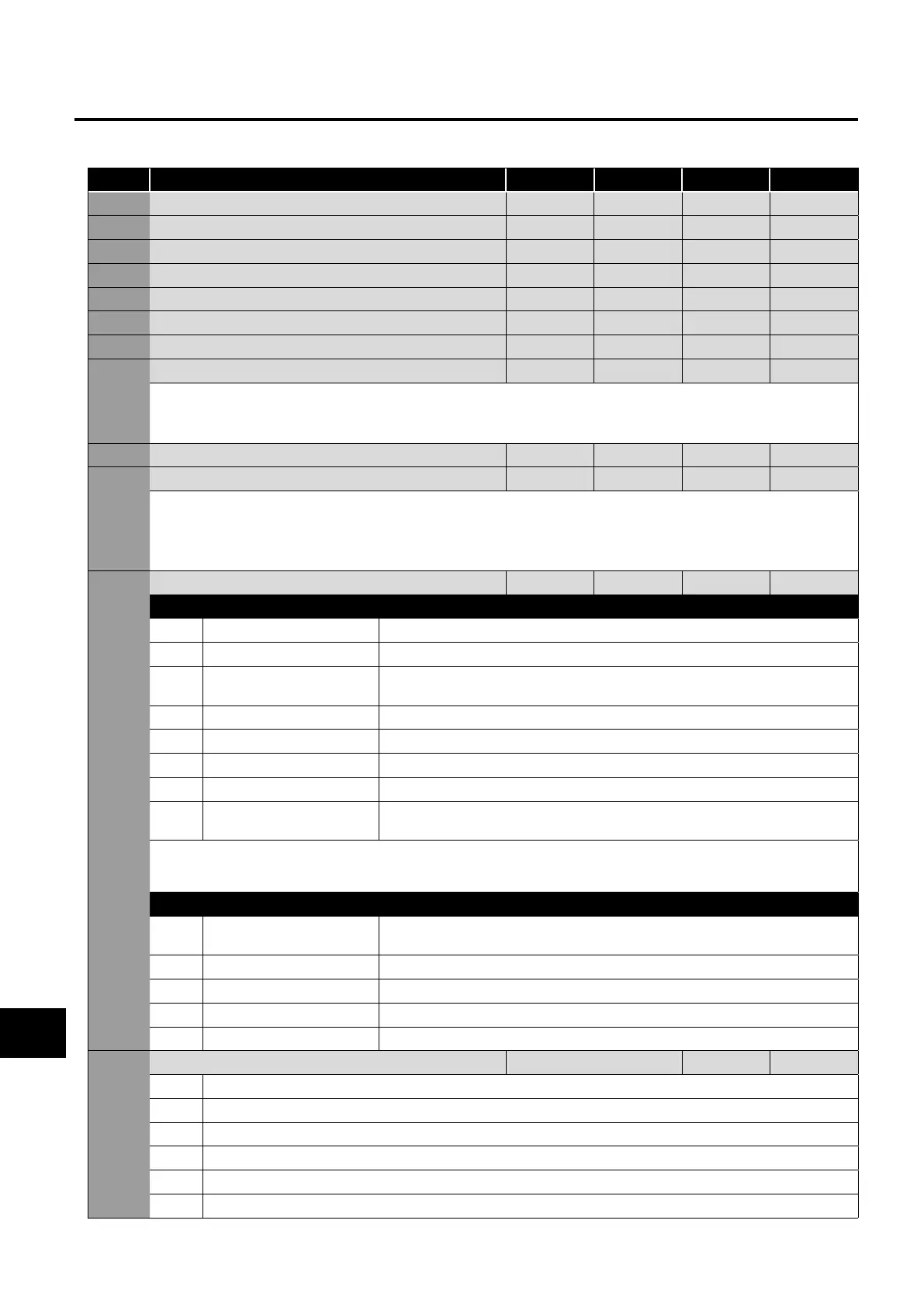
Par Parameter Name Minimum Maximum Default Units
P2-01 Preset / Jog Frequency / Speed 1 P1-02 P1-01 5.0 Hz / Rpm
P2-02 Preset / Jog Frequency / Speed 2 P1-02 P1-01 10.0 Hz / Rpm
P2-03 Preset / Jog Frequency / Speed 3 P1-02 P1-01 25.0 Hz / Rpm
P2-04 Preset / Jog Frequency / Speed 4 P1-02 P1-01 50.0 (60.0) Hz / Rpm
P2-05 Preset / Jog Frequency / Speed 5 P1-02 P1-01 0.0 Hz / Rpm
P2-06 Preset / Jog Frequency / Speed 6 P1-02 P1-01 0.0 Hz / Rpm
P2-07 Preset / Jog Frequency / Speed 7 P1-02 P1-01 0.0 Hz / Rpm
P2-08 Preset / Jog Frequency / Speed 8 P1-02 P1-01 0.0 Hz / Rpm
Preset Speeds / Frequencies selected by digital inputs depending on the setting of P1-13.
If P1-10 = 0, the values are entered as Hz. If P1-10 > 0, the values are entered as Rpm.
Setting a negative value will reverse the direction of motor rotation.
P2-09 Skip Frequency Centre Point P1-02 P1-01 0.0 Hz / Rpm
P2-10 Skip Frequency Band Width 0.0 P1-01 0.0 Hz / Rpm
The Skip Frequency function is used to avoid the Optidrive operating at a certain output frequency, for example at a frequency which
causes mechanical resonance in a particular machine. Parameter P2-09 defines the centre point of the skip frequency band, and is
used conjunction with P2-10. The Optidrive output frequency will ramp through the defined band at the rates set in P1-03 and P1-04
respectively, and will not hold any output frequency within the defined band. If the frequency reference applied to the drive is within
the band, the Optidrive output frequency will remain at the upper or lower limit of the band.
P2-11 Analog Output 1 (Terminal 8) Function Select 0 11 8 -
Digital Output Mode. Logic 1 = +24V DC
0 Drive Enabled (Running) Logic 1 when the Optidrive is enabled (Running).
1 Drive Healthy Logic 1 When no Fault condition exists on the drive.
2 At Target Frequency
(Speed)
Logic 1 when the output frequency matches the setpoint frequency.
3 Output Frequency > 0.0 Logic 1 when the motor runs above zero speed.
4
Output Frequency >= Limit
Logic 1 when the motor speed exceeds the adjustable limit.
5 Output Current >= Limit Logic 1 when the motor current exceeds the adjustable limit.
6 Motor Torque >= Limit Logic when the motor torque exceeds the adjustable limit.
7 Analog Input 2 Signal
Level >= Limit
Logic when the signal applied to the Analog Input 2 exceeds the adjustable limit.
NOTE When using settings 4 – 7, parameters P2-16 and P2-17 must be used together to control the behaviour. The output will switch
to Logic 1 when the selected signal exceeds the value programmed in P2-16, and return to Logic 0 when the signal falls below the
value programmed in P2-17.
Analog Output Mode
8 Output Frequency
(Motor Speed)
0 to P-01.
9 Output (Motor) Current 0 to 200% of P1-08.
10
Motor Torque
0 to 200% of motor rated torque.
11 Output (Motor) Power 0 to 150% of drive rated power.
12 PID Output Output from the internal PID Controller, 0 – 100%.
P2-12 Analog Output 1 (Terminal 8) Format See Below
-
0 to10V
0 to 20mA
4 to 20mA
10 to 0V
20 to 0mA
20 to 4mA

 Loading...
