36 | Optidrive P2 User Guide | Version 3.00 www.invertekdrives.com
6
Parameters
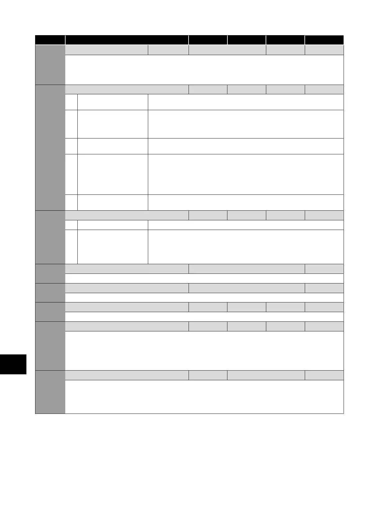
Par. Description Minimum Maximum Default Units
P1-04 Deceleration Ramp Time See Below 5.0 / 10.0 Seconds
Deceleration ramp time from base speed (P1-09) to standstill in seconds. When set to zero, fastest possible ramp time without trip is
activated.
FS2 & FS3 : 5.0 Seconds Default Setting, 0.01 Seconds Resolution, 600.0 Seconds Maximum.
FS4 – FS7 : 10.0 Seconds Default Setting, 0.1 Seconds Resolution, 6000.0 Seconds Maximum.
P1-05 Stop Mode 0 3 0 -
0 Ramp To Stop
When the enable signal is removed, the drive will ramp to stop, with the rate controlled by
P1-04 as described above. In this mode, the drive brake transistor (where fitted) is disabled.
1 Coast to Stop When the enable signal is removed, the drive output is immediately disabled, and the motor
will coast (freewheel) to stop. If the load can continue to rotate due to inertia, and the drive
may possibly be re-enabled whilst the motor is still rotating, the spin start function (P2-26)
should be enabled. In this mode, the drive brake transistor (where fitted) is disabled.
2 Ramp To Stop When the enable signal is removed, the drive will ramp to stop, with the rate controlled by
P1-04 as described above. The Optidrive Brake chopper is also enabled in this mode.
3 Coast to Stop When the enable signal is removed, the drive output is immediately disabled, and the motor
will coast (freewheel) to stop. If the load can continue to rotate due to inertia, and the drive
may possibly be re-enabled whilst the motor is still rotating, the spin start function (P2-
26) should be enabled. The drive brake chopper is enabled in this mode, however it will
only activate when required during a change in the drive frequency setpoint, and will not
activate when stopping.
4 AC Flux Braking As Option 0, but additionally, AC Flux braking is used to increase the available braking
torque.
P1-06 Energy Optimiser 0 1 0 -
0 Disabled
1 Enabled When enabled, the Energy Optimiser attempts to reduce the overall energy consumed by
the drive and motor when operating at constant speeds and light loads. The output voltage
applied to the motor is reduced. The Energy Optimiser is intended for applications where
the drive may operate for some periods of time with constant speed and light motor load,
whether constant or variable torque.
P1-07 Motor Rated Voltage Drive Rating Dependent Volts
This parameter should be set to the rated (nameplate) voltage of the motor (Volts).
P1-08 Motor Rated Current Drive Rating Dependent Amps
This parameter should be set to the rated (nameplate) current of the motor.
P1-09 Motor Rated Frequency 10 500 50 (60) Hz
This parameter should be set to the rated (nameplate) current of the motor
P1-10 Motor Rated Speed 0 30000 0 RPM
This parameter can optionally be set to the rated (nameplate) rpm of the motor. When set to the default value of zero, all speed
related parameters are displayed in Hz, and the slip compensation for the motor is disabled. Entering the value from the motor
nameplate enables the slip compensation function, and the Optidrive display will now show motor speed in estimated rpm. All
speed related parameters, such as Minimum and Maximum Speed, Preset Speeds etc. will also be displayed in Rpm.
NOTE When the drive is operated with the optional Encoder Feedback Interface, this parameter must be set to the correct
nameplate Rpm of the connected motor.
P1-11 V/F Mode Voltage Boost 0.0 Drive Rating Dependent %
Voltage boost is used to increase the applied motor voltage at low output frequencies, in order to improve low speed and starting
torque. Excessive voltage boost levels may result in increased motor current and temperature, and force ventilation of the motor may
be required.
An automatic setting () is also possible, whereby the Optidrive will automatically adjust this parameter based on the motor
parameters measured during an autotune.
 Loading...

