Sensor Installation
Modline 5
Rev. L6 Feb 2017 25
Figure 8: Laser Sight
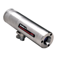
If looking through a sight tube or sight hole, position, align and rotate the Sensor and Sight tube to
center the laser image in the field of view.
The Sensor is a Class II Laser Product with the Laser Sight option installed, see section 5.11 Laser
Sighting Operation, page 102 of this manual for safe and full operating instructions. Install Sensor and
setup Laser operating procedures so that personnel are not exposed to the laser beam at any time
whether the Laser is energized remotely or at the Sensor Rear Panel.
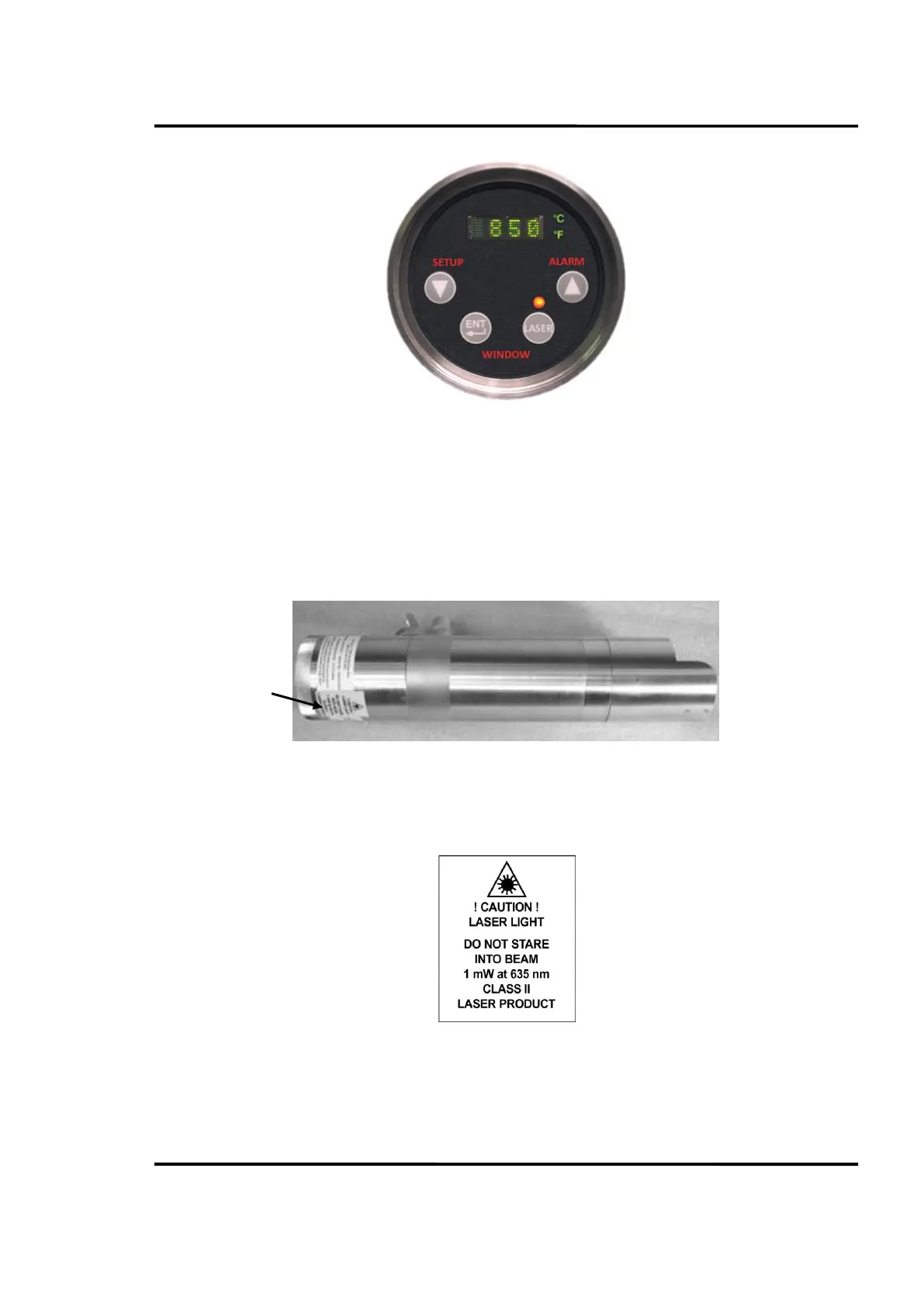
Figure 9: Sensor Laser Label
The sensor label is shown in detail in Figure 10.
Figure 10: Sensor Laser Label in Detail