12 Freddy
Positioning
It is recommended to avoid positioning the appliance in
closed environments with high temperatures and poor
air circulation, exposed to direct sunlight or weather
agents, and near heat sources.
When choosing the positioning place, check also
that there is enough space to allow the door
opening. The power cable is 2-m long and for
problems linked to overheating it is not possible to
use extensions or small cables to adjust its length.
When installing FREDDY take the position of the sockets
into account.
Furthermore, we recommend to strictly follow the
layouts below.
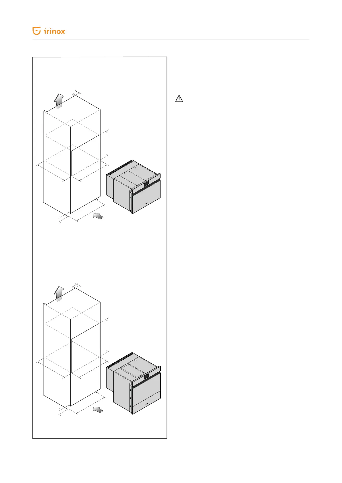
For a correct air circulation, the rear wall of the
compartment must be left open and an air outlet of
minimum 300 sq.cm must be provided (see Fig. 5 -
Installation details); once the appliance is positioned in
the compartment, secure it on the front with 4/6 self-
threading screws (supplied) using the preset holes.
Note: we recommend using support brackets, to be
ordered separately, to be xed to the side of the unit
if Freddy 45R is matched to a compensator or Zero
15R.
Avoid placing Freddy R above heat sources (ovens,
microwaves, etc.) to preserve
its operation and performance.
Ambient temperature and air recirculation
The air temperature of the operating environment must
not exceed 32 °C. The yields stated are not guaranteed
above this temperature.
Final checks
Perform the following checks before turning on
FREDDY:
• If during transport the appliance has been laid
horizontally on one side or kept at a temperature
lower than 10 °C, wait for at least 4 hours before
turning it on. Check the correct electrical connection.
Control and safety systems
• Clixon compressor that triggers in case of overload or
operation anomalies.
• Chamber temperature control managed via electronic
board through an inner temperature probe.
40 mm
50 mm
Fig. 5
Dettagli di installazione FREDDY 45 R
Dettagli di installazione FREDDY 60 R
Uscita aria
Uscita aria
Entrata aria
Entrata aria
40 mm
50 mm
440 mm
560 mm
560 mm
560 mm
580 mm
585 mm
560 mm
580 mm
Fig. 5
Air inlet
Air inlet
Air outlet
Air outlet
FREDDY 45 R installation details
FREDDY 60 R installation details
 Loading...