INSTRUMENTS & CONTROLS
27
NOTE: PTO switch, 4, must be used in conjunction with
rear and mid PTO selector lever, to left and
under operator's seat, when rear and mid PTO
used. Refer to “Operation” section for complete
details. When PTO controlswitch is “ON”, the
engine cannot be started. Always switch off PTO
and place range gear shift lever in neutral to
start engine.
WARNING: always shut off PTO and shut off
Tractor engine before servicing PTO driven
implment. Allow movement and motion to
stop before leaving operator's seat.
MAIN CLUTCH PEDAL (Mechanical Transmission)
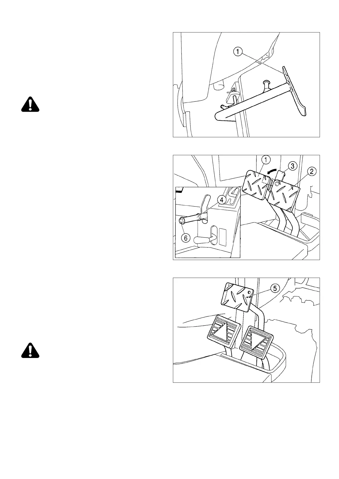
FIG. 17: Foot pedal (1) disengages engine from
transmission when fully depressed, to permit engine start-
ing, selecting / changing gears and stopping Tractor
movement. PTO and four-wheel drive selection (if
equipped) also requires clutch disengagement. Slowly
raising the pedal will engage clutch and resume power to
transmission and PTO.
NOTE: Clutch pedal should be depressed quickly to
prevent abnormal wear. Clutch pedal should be
raised smoothly to prevent sudden movement.
DO NOT "ride" clutch pedal with your foot.
Hydrosttic drive models have no clutch pedal.
IMPORTANT: Correct clutch pedal free-play adjustment
is a must. Consult "Maintenance" section.
BRAKES
Brake Pedals
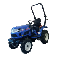
FIG.18 & 19: Inner brake pedal (1) and outer brake
pedal (2) independently control the respective left and
right wheel brakes, to assist in turning. During Tractor
transport or high speed operation, brake pedals must be
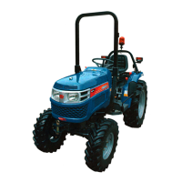
latched together using interlocking plate (3).Hydrostatic
models do not have individuai wheel brakes but single
brake pedal (5).
CAUTION: Do not use individual wheel
brakes for transporting or operating at high
speed. Always latch pedals together using
interlocking plate, 3. Make sure brakes are
adjusted evenly.
Parking Brakes
FIG. 18: To engage parking brakes, pull upward on
the parking lever (4) to lock brakes in applied position.
To disengage parking brakes, push in on release but-
ton (6) and lower the lever (4) to the released position.
FIG. 17
FIG. 18 (Mechanical transmission)
FIG. 19 (Hydrostatic transmission)



 To Next Page